Don't think you need the resistor just the ground. It's just a reference point (0volts) so a probe has a negative reference.
Don't think you need the resistor just the ground. It's just a reference point (0volts) so a probe has a negative reference.
Yes that is true (in this case), but in some circuits it matters, this was just to demonstrate that in all cases where simulation has problems to calculate levels (most obviously when there is no ground connection at all) a 'extreme' resistor may help, while that same resistor will not influence the circuit.
Graphing THD
When measuring THD, is there a way to graph the results? Normally I use CTL-L to bring up a dialog which shows a table of numeric values (harmonics vs. distortion values). Is there a way to easily plot that table, so that frequency is the x axis and THD is the y axis?
When measuring THD, is there a way to graph the results? Normally I use CTL-L to bring up a dialog which shows a table of numeric values (harmonics vs. distortion values). Is there a way to easily plot that table, so that frequency is the x axis and THD is the y axis?
LT XVII anomaly
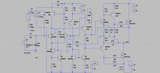
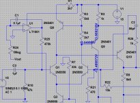
Would you call this a bug ? Its a simulated circuit of a commercial amp.
When I run a .op command and look at the voltages of Q9 they are correct. When I hover over the nodes they display correctly, but when I click to attach the voltage I always get a 0V for Q9 collector. If I then run the sim again, Q9 voltage repopulate correctly.
In fact it gets even weirder. If I run the sim from scratch again and this time attach the voltage to Q6 and Q7 base I see the correct voltage. Now click Q9 collector and the attached voltage is zero again but now it changes Q6/7 back to zero.
Odd.
(all default library models so should run straight off. Haven't tried LT IV as I haven't got it installed on my later PC's)
Attachments
I see what you mean 🙂 It hadn't registered with that the node was changing when the sim ran, a problem I've never really come across before.
 Thanks again.
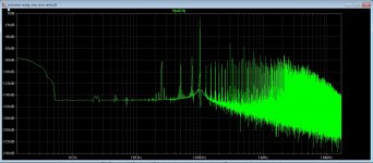
Thanks again.As you guys are real ltpspice specialists I have a question about distortion, I have discover that the voltage source has also high distortion, and so I do not now what amp has, is there something adjustable there? to get clean source.
thanks.
thanks.
Attachments
Taming LTSpice Distortion
You need to add two things:
1. the following statement as LTSPICE directive (without quotes)
".options plotwinsize 0"
2. Make sure that your max time-step is not more than 1/1000 of the period of the wave for which you measure distortion...e.g. for 1 kHz sine wave, make max timestep 1e-6
That should get you there.
Thanks I did try and it works, however the second harmonic stays higher then the rest on the voltagesource, but it is much better.
regards
Attachments
Mooly's results are what I'd expect for a source. On a sim I ran with 1 kHz and 1us minimum time step I got all harmonics about 176 dB below the fundamental.
Try adding .options numdgt=7
This increases the numerical accuracy.
If your source has series impedance, it may be harmonics in the input current of your circuit.
This increases the numerical accuracy.
If your source has series impedance, it may be harmonics in the input current of your circuit.
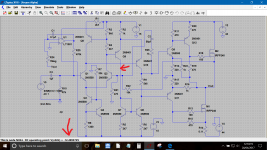
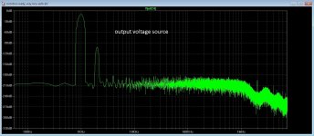
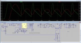
I get this when I do try that, it is however considerable better. picture two is a inverter smps, I do see the feedback give a changing line (red) while it needs constant voltage, I have for test drawn a existing voltage feedback who normally keep voltage straight, here in sim it do go up and down between 120 and 180 amps, it is shure becaue of the simulation, maybe it sees a kind of resonance in feedback line, while in realtime it works perfect giving a straight stable output voltage. Maybe LTspice is not suitable for smps simulation and do I need a other wone like tina or such.
Thanks for the help, so I learn also the tricks from ltspice.
regards
Thanks for the help, so I learn also the tricks from ltspice.
regards
Attachments
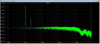
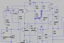
I have found the reason why, also the setup keantoken give did help a lot, I have put a extra voltage source and put the middle on ground to make a diff signal.
That did the trick so it was serie impedance problem, again something learned thanks.
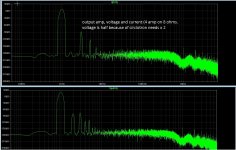
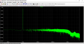
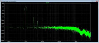
pictures are input and output amp, last picture is output with 1.2 amps in the load, the other where higher ouput current and more distortion, however only uneven ones because circlotron cancels even harmonics..
Now I can go on, and watch out what to do with that LTspice. Distortion for IRFP240 or 2SK1058 did not differ for each other much.
I have seen somewhere that I can actually measure distortion in text form,? LTspice do print it, how?.
regards
That did the trick so it was serie impedance problem, again something learned thanks.
pictures are input and output amp, last picture is output with 1.2 amps in the load, the other where higher ouput current and more distortion, however only uneven ones because circlotron cancels even harmonics..
Now I can go on, and watch out what to do with that LTspice. Distortion for IRFP240 or 2SK1058 did not differ for each other much.
I have seen somewhere that I can actually measure distortion in text form,? LTspice do print it, how?.
regards
Attachments


Last edited:
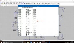
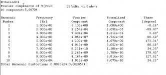
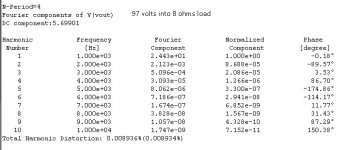
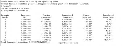
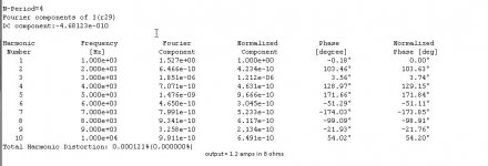
As your fundamental is 1kHz you need to add the following .op command
.four 1khz 10 4 v(vout)
That will show the distortion (first 10 harmonics) from 1kHz upward. You need to label the node of interest on the circuit as vout
Edit... you could also use .four 1khz 10 4 i(R29) for your circuit.
Right click the circuit after running the simulation and look at the spice error log for the results.
Last edited:
As your fundamental is 1kHz you need to add the following .op command
.four 1khz 10 4 v(vout)
That will show the distortion (first 10 harmonics) from 1kHz upward. You need to label the node of interest on the circuit as vout
Edit... you could also use .four 1khz 10 4 i(R29) for your circuit.
Right click the circuit after running the simulation and look at the spice error log for the results.
Oke thanks.
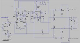
I do use R29 because I have balanced output, but can also try Vout for single ended output info.
Did some sims, Vout is unbalanced so no harmonics are canceld out, with the R29 output it is balanced and so harmonics are quite low for almost full output of 6 amps
in 8 ohms.
info on pics, I put them also on mine thread.
Thanks for the help, this way I learn LTspice better because also the smps needs work, want make one for a hybrid amplifier 2 x 65 volts 20 amps, 1 x 300 volts 0.3 amps, and 2 x 7.5 volts 5 amps. for this amp I need only 2 x 65 volts 20 amps and 2 x 15 volts 400 mA auxiliary voltage as backup if using opamps for balance to unbalance..
regards
Attachments
Last edited:
Where can I find an older version for Windows XP? I need to re-format the HD and I lost my current version.
many thanks in advance.
many thanks in advance.
Attachments

- Home
- Design & Build
- Software Tools
- Installing and using LTspice IV (now including LTXVII), From beginner to advanced