Mooly,
thank you for the graphs, I was under the impression that the amplitude should be brought up to the fullest so that the output waves may look triangle like.
The rejected no.that I was referring is indicated in the pop up results box after a simulation ends, when you scroll down to the window there you see rejected-0 [0 in ac simulation i guess] but in my other sim runs I get random numbers e.g rejected-22, 26, 345 etc.
...[just finished downloading the latest update of LT17 as of Feb.17....will give it another try]
Good news!
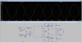
The update of Feb. 17 seemed to work nicely...except that I get a strange AC analysis in this schematic. 😕 This was passed on to me by member bimo [hadn't get a response from him yet in my query at fhe SS forum]
Mooly,
...can you help me check it if I made some errors in the parameters? I know some sim runs needed some parameters to be put to the sign ; so that the . parameters will become the prime spice directives. Transient analysis works fine. I did some component changes under LT17.
Thanks a lot!
Attachments

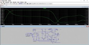
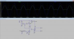
...based on your graph I think my problem lies on one of the parameters. Left graph seemed to be correct, in my simulation the graph falls down in the middle part and it is giving me minus db...guess i need more time studying with the given parameters in the schematic it is also too complex for me...🙄
🙂
🙂
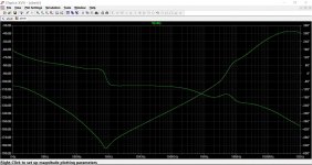
..yes you are quite right Im still figuring out how to work with them, schematic is very different than most schematic that Im seeing in the forum. I do think some parameters should be deactivated to run a proper ac analysis, notice the multiple Vin, 3 AC input sources and 2 dc pulse...
Bob Cordells book is well worth a read on all this, and Bob has examples to run that are available from his site.

Hi Mooly,
I am slowly reading into parts of this thread & would just like to say that I find it to be very helpful & informative ... Thanks for the initiative ;-)
Cheers,
Jesper
I am slowly reading into parts of this thread & would just like to say that I find it to be very helpful & informative ... Thanks for the initiative ;-)
Cheers,
Jesper
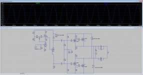
I have a question about how this do happen, because it just has to work like it do in multisim, I get no fase splitting but some strange other effects, have try al kinds of tube models, but when I remove the mosfet in voltage amplifier stage it works in ltspice, however I had it also work some time ago.
And as I do also now sometimes I do look over things, most the simple ones who you look at a other way.
very very strange sometimes that simulation, but maybe some experienced simo's can help of advice..
You can see on pictures that fase shift do not work on some, the version who did I had redraw from scratch, however later it did wrong again.
thanks..
Attachments
Do you mean that when you run the simulation multiple times that you get two different results ?
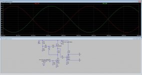
Pictures 3 and 4 are subtly different and also have different 'output' voltages for one thing. You would have to label the output of the caps (like in picture 3) so that we could be sure you are looking at the same points.
Maybe I'm not understanding the question 🙂 and I've no answer if you are getting different results either.
Do you mean that when you run the simulation multiple times that you get two different results ?
Pictures 3 and 4 are subtly different and also have different 'output' voltages for one thing. You would have to label the output of the caps (like in picture 3) so that we could be sure you are looking at the same points.
Maybe I'm not understanding the question 🙂 and I've no answer if you are getting different results either.
It seems that I did have to much voltage on the grid of splitter tube as @mayborn did say, making the tube saturated and so not fase splitting, a resistor divider can bu used as I need higher voltage for the amplier tube section, otherwise I get to low voltage there in mine opinion.
There is different in ltspice or multisim, yes, even when draw all the same, I think the models are different then and not a faulty ltspice.
All the outputs are taken from the caps like in picture 3 I did forgot to mention that.
thans for posting.
Last edited:
Two same schematics, same adjustments in ltspice, first is ltspice 32bit, second and thirt is 64bit, both has same adjustments but the 64bit do not sim well, also both have the same library parts.
Not oke the second two 64 bit sims.
Maybe it is because both are installed, what I think it is not a problem.
regards
Not oke the second two 64 bit sims.
Maybe it is because both are installed, what I think it is not a problem.
regards
Attachments


Last edited:

I'm still not following you tbh.
The 1st schematic is totally different to the 2nd and 3rd ones, and the 2nd and 3rd are showing voltage and current respectively as the displayed trace.
No, yes 🙂
The 1st schematic is totally different to the 2nd and 3rd ones, and the 2nd and 3rd are showing voltage and current respectively as the displayed trace.
No, yes 🙂
I'm still not following you tbh.
The 1st schematic is totally different to the 2nd and 3rd ones, and the 2nd and 3rd are showing voltage and current respectively as the displayed trace.
No, yes 🙂
Yes is shows current or voltage, what I did probe, but same outcome of signal, it is model who do make trouble, now it did work, I go use one ltspice, just the old 32bit who do normal.
regards
I get very strange things, it do simulate nS do not go on, and when do skip initial operation point fir example it complaine about floating nodes, strange because it happen suddenly, I have simulated it yesterday without problems, can it be that the HD is bad saving files and contain errors of such.
I have tryed everything it just sims extreeeeem slow and only nSeconds and give error after that, signals are just bargage.
I have tryed the 64 bit version, this version crash all the time. Mine pc do work oke further on, so no trouble with windows and such.
regards
I have tryed everything it just sims extreeeeem slow and only nSeconds and give error after that, signals are just bargage.
I have tryed the 64 bit version, this version crash all the time. Mine pc do work oke further on, so no trouble with windows and such.
regards
Attachments
It seems to mee that the part, shown in the picture, is floating, just ad a large resistor, like here 1G, to ground and it will be fixed (un-floated). Some parts are not shown (to me) while they are not included with the schematic (simulation) file. Remember that any point in the circuit must have a galvanic connection to ground.
Attachments
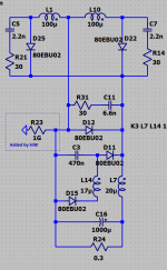
It seems to mee that the part, shown in the picture, is floating, just ad a large resistor, like here 1G, to ground and it will be fixed (un-floated). Some parts are not shown (to me) while they are not included with the schematic (simulation) file. Remember that any point in the circuit must have a galvanic connection to ground.
Yehh thanks, it are the small things who matter, not the big ones Mr-Murphy.😀
- Home
- Design & Build
- Software Tools
- Installing and using LTspice IV (now including LTXVII), From beginner to advanced