Ahem ... I think I forgot to explicitly connect the substrate on the symbol. I will try again, although the Supertex model didn't complain.
Edit: yes that was it. Both models OK now. Thanks guys.
Jan
Edit: yes that was it. Both models OK now. Thanks guys.
Jan
Do not think so, that is why I believe he added it to your documents directory. I hope that is the case, if not make a copy before you do the update.
Jan, there is a DN2540 model in my thread, if that is what you're after.
Better power MOSFET models in LTSpice
Better power MOSFET models in LTSpice
Jan, there is a DN2540 model in my thread, if that is what you're after.
Better power MOSFET models in LTSpice
Wow, I actually posted that myself. I'm getting old. Really.
Jan
I did that too, should I be worried?
But you remembered! That's the crucial difference ;-)
Hi all guys
I had simulate multilevel pwm btl outputs, however now I will go to the final part, problem is, it is a capacitor version and a cascaded version output mosfet stage, the cascaded has floating supply's two for 5 level, and I can not find a suitable mosfet drive ic, or do I need to go discrete? one way I can think of is a insulated driver who uses a optocoupler inside, but are these capacble of giving nice fast transistions of blockwave who is very important.
The fling cap has also some problems, but is not floating outputs, here I think it is needed to use driver ic for each mosfet, cont an combined one.
regards
thanks.
Attachments
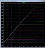
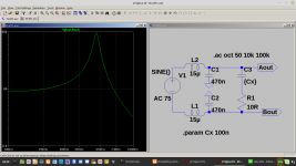
I simulated your output filter with snubber.
At resonance voltage peaks up to +/- 880V.
In this theoretical case your snubber resistor and all filter caps might explode.
In case your input signal is strictly band limited to 20kHz, the resonance will not be excited.
But at 20kHz and full power your snubber resistor will dissipate 10Watts as well.
So these kind of snubbers are USELESS.
just my 2c
Attachments
Last edited:
I simulated your output filter with snubber.
At resonance voltage peaks up to +/- 880V.
In this theoretical case your snubber resistor and all filter caps might explode.
In case your input signal is strictly band limited to 20kHz, the resonance will not be excited.
But at 20kHz and full power your snubber resistor will dissipate 10Watts as well.
So these kind of snubbers are USELESS.
just my 2c
I do have talking about a class d amplifier, Oke, when using multilevel the low pass can be set to a very high -3db point, so getting it excited will then never happen I hope.
The snubber is not the right one, but later on when go with it then we see of ourselfs what happens.
I have only the question not yet answered what way I can drive the mosfets, because of the floating voltages of outputs, I think I need insolated types or even a driver for each mosfet alone and not like a irs 2011 or such.
Sorry for the unclear post.
regards
Last edited:
For the bandwith concerns and resoance, the low pass is 120 Khz -3dB with a 5 level class d who has a output frequency of 1.6 Mhz with 400 khz input. This is not the example you did simulate the resonance and 880 volts out.
That is why I am interesed to build one some day, now first the resonance smps done for the voltages to tubes in the hybrid, and one for outputs.
regards
That is why I am interesed to build one some day, now first the resonance smps done for the voltages to tubes in the hybrid, and one for outputs.
regards
LTSpice step skipping
Hi
I have a question about ".step param …" and skipping. I looked everywhere for this. Maybe I missed it ?
I have often encountered, that a simulation can take a very long time, fx when an amplifier gets unstable using the supplied values for a given step.
Let's say we try out different Miller caps for an amplifier using ".step param Cmiller list 4p7 10p 15p 22p 27p 33p".
When we get to step 3 it immidiatly starts to oscillates badly, taking a lot of time for the "15p" value.
Is it possible to skip the rest of the simulation for this one step and let it continue to the next step ?
/Jørgen
____________________________________
Don't trust atoms. They make up everything.
Hey there!
I'm hoping this message is sufficiently appropriate for this page, I can't seem to find a better one.
I'm afraid that over having but very few tools, I also have a prehistoric computer, and cannot seem to find a version of LTSpice that works on my computer : because I have a Mac running on OS 10.6.8 (I think that's Snow Leopard), I cannot appear to get LTSpice to work on my device! Does anyone know where I can find an older version of LTSpice? Or another software that I can use for the same purposes? I found MacSpice, but it appears a little complicated to my bird brain, it looks a lot like programming to me. I've done a little research in both trying to use MacSpice and trying to find a compatible LTSpice version, but I'm afraid that the very little optimisim I found encouraged me to ask you for alternatives.
If anyone has any answers, thanks a lot!
Jonah G.
How changing LTspice DC-output listing
When in LTspice I do a DC opt run, its listing displays what I will call "scientific notation" (like: "7.2e-009 voltage").
How can I change this into something more readable like mV or uV? Same with the currents.
When in LTspice I do a DC opt run, its listing displays what I will call "scientific notation" (like: "7.2e-009 voltage").
How can I change this into something more readable like mV or uV? Same with the currents.

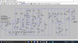
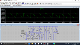
These files are for someone who asked how it was done 😉
The regulator actually won't self start in simulation... I wonder if any real ones are the same 😱 and it needs the 10k at the extreme right of the diagram to work.
The second sim must be run as a 'transient' type. A DC operating point sim will just return zero for all the voltages because there is no DC voltage source to power the circuit.
There is no audio output on the AC sim which is probably because the circuit needs more time to stabilise... I'll leave that one up to you to experiment with.
Remember that audio ground is the ground reference of the sim and so the negative input to the regulator (the bottom end of the 95 volt supply) will actually read as a negative voltage with respect to ground. The positive rail (the top end of the 95 volt supply) will read correctly as 67 volts.
Attachments

- Home
- Design & Build
- Software Tools
- Installing and using LTspice IV (now including LTXVII), From beginner to advanced