You do not need the 'curlies' in a .param statement.
You do need the 'curlies' when substituting a [.param] value in most commands/directives.
P.s. evalper has an error, it is the 'extra' 'm' that follows the expression.
P.s. the macro[param etc] evaluation-engine is of the type 'merge-first-then-evaluate' when an error happens the evaluator will report the statement in which it occurred, not where it originated (this can be puzzling at times 🙂)
P.p.s.
Like in:
.param a = error
.param b = 6
.param c = a + b
May (but not surely) report an error in the '.param c...' statement and may never report an error in the '.param a...' statement, this gets real complicated [to solve] when many statements are 'mixed' spread over a large solution, it would be nice if the evaluator was a bit 'modernized'.
Yes I got that finally. I always had problems in my programming with pointers-to-array-of-pointers-to-arrays as well

Jan
Jan, guess what? I originally authored that .param string. 😉
Some of the old versions still popping up in simulations aren't perfect. Might still not be perfect.
FdW, I get the impression you have some valid criticisms of how I do it based on your knowledge, but maybe you don't want to get into a discussion on it.
Here is what I currently have. I added a trtol line based on empirical tests to find out what seems to work best in empirical tests. Optimizing trtol can get you to -300db in many cases. It doesn't work well if you use more than 10 test cycles however.
.options
+ plotwinsize=0
+ numdgt=7
+ noopiter
+ ptrantau=0
+ trtol={8.192/2**FFT}
.param
+ numcyc=10
+ dlycyc=1
+ FFT=16
+ simtime=numcyc/Freq+dlytime
+ dlytime=dlycyc/Freq
+ timestep=(simtime-dlytime)/2**FFT
.four {Freq} V(Vin) V(Vfb) nperiods=-1
.four {Freq} 4 V(Vfb) nperiods=-1
.param F=1k
...FdW, I get the impression you have some valid criticisms of how I do it based on your knowledge, but maybe you don't want to get into a discussion on it...
Just tell me/us what parts of your simulation behaviors you are pointing at as I have no idea what you mean or where that criticism is.
About the "but maybe you don't want to get into a discussion on it" part; Maybe 🙂 but then, more than 40 years of these discussions [in forums like these] have learned me some
You do not need to manipulate the 'trtol' parameter to get at -300dB.
I was working on a paper that I [once] liked to publish [Jan's magazine would not have been a bad place]. For this I developed a 'standard' [default simulation model] setup for low...high precision an high...low speed by changing a single setting.
I add the, current, version to this message, it combines many settings that I learned from reading this form and using spice [LTspice] for a long time. It is not perfect [and will never be] take it as it is and I will answer questions about it [if presented here].
It was posted [in an earlier incarnation] as part of this posting
Installing and using LTspice IV (now including LTXVII). From beginner to advanced.
Attachments

Last edited:
No, -300db is not necessary, but if you ever need to run a long simulation, efficient configuration of the simulator will reduce the time necessary to get valid results.
There are also danger zones in the configuration where you will get harmonics that shouldn't be there even though the simulation seems fine.
Thanks for the file. I will study it...
There are also danger zones in the configuration where you will get harmonics that shouldn't be there even though the simulation seems fine.
Thanks for the file. I will study it...
Last edited:
Some thoughts.
1: Including active non-sine generators on the schematic reduces accuracy because they trigger a timestep change. Deleting the non-sine generators from the schematic improves resolution at tolerable simulation speeds - 2.5 seconds for a -240db noise floor on a Kuartlotron simulation. Also, after the timestep changes the data points are no longer synchronized to the FFT points; I believe this is a quirk of the LTSpice algorithm and am not sure if it can be changed. LTSpice is optimized for SMPS after all.
2: Your FFT parameter determines the number of points per cycle. Since the FFT is taken over the whole simulation, and the number of cycles is variable, the relationship with the FFT bins is broken and ruins the point of calling this parameter FFT. And if you set the number of cycles to 7 for instance, you will lose the time alignment of the data points because 1/(7x2**16) is not an integer ratio of 1/(2**16)
3: sim_precision changes both reltol and the timestep. So how did you determine how much reltol should be increased in combination with time resolution? If I want to see oscillation behavior I don't necessarily want to increase numerical resolution along with time resolution. I could just change FFT, but then I understand how the parameters work mathematically. A lot of users won't, and this is compounded by the fact that FFT is misleadingly named; any assumptions the user makes about the FFT parameter probably will be false.
Jan, guess what? I originally authored that .param string. 😉
Actually Ian told me that he couldn't remember the exact source but that it might have been you 🙂
Jan
Anthony, on the max timestep stuff. Setting this value synchronized to the # of data points over the sim time only works, imho, if the sim consistently uses only the max timestep. How do you know/ensure that it doesn't use a smaller timestep at some point and ruin the sync?
Jan
Jan
Actually I think my point #2 is false. I think FdW's simulation does align the points correctly (assuming the integrator doesn't mess them up), but it's a bit awkard (to me) the way it does it.
As for the changing timestep, that's what I've wanted to find out. If you run FdW's simulation with the included non-sine waveform generators, you'll find that for instance on a square corner, the datapoints will suddenly get closer together and when they spread out again, they're not aligned with the ones preceeding the corner, although they are still the same distance apart. This shows up as an increased noise floor in the FFT and you can end up increasing resolution to compensate.
One solution is to set the max timestep so short that the integrator never feels the need to change it. But if you have abrupt waveforms in your simulation, you may end up having to increase it by many times - which means the simulator is not running as efficiently as perhaps it could if the integrator took care to preserve the FFT alignment of the datapoints. But perhaps this is intentional and works better for SMPS simulations which LTSpice was designed for.
The second thing to do is to disable square wave and other sharp waveform generators on the schematic which will unnecessarily trigger the integrator, when you want to see harmonic behavior. It's not enough to just set the generators to zero. Even then I have noticed they will have an effect. Better to set the frequency to a wavelength longer than the simulation and give it a phase lead so the simulation doesn't start at the beginning of the square.
I suspect that choosing the right value for trtol will cause it to ramp the timestep up by an amount proportional to the max timestep, but I am not sure whether this works consistently for different simulations.
At the other extreme, as an experiment you can turn off maxstep and just set trtol to a low number like 100u or however low it takes to slow the simulation down to several seconds. You will notice that the simulation progress gets jerky and the timestep ramps up and down greatly as the integrator sets a very large timestep on the smooth parts of the simulation. Then you can get really outrageous levels of harmonics from computational errors.
1: Including active non-sine generators on the schematic reduces accuracy because they trigger a timestep change. Deleting the non-sine generators from the schematic improves resolution at tolerable simulation speeds - 2.5 seconds for a -240db noise floor on a Kuartlotron simulation. Also, after the timestep changes the data points are no longer synchronized to the FFT points; I believe this is a quirk of the LTSpice algorithm and am not sure if it can be changed. LTSpice is optimized for SMPS after all.
First of all, the posted file is intended as a learning tool, and in addition to that as a file that can be used as a starting point when setting up a new simulation (simulated circuit).
When the tool is used in 'LoRes'-mode (e.g. sim_precision is less than or equal to 1) the 'pointy'-generators (basically all other than the sinewave generator) are of no concern, when running 'HiRes'-simulations it would be smart to remove the 'extra' (not in use) generators, this for all the reasons mentioned above (by keantoken)
2: Your FFT parameter determines the number of points per cycle. Since the FFT is taken over the whole simulation, and the number of cycles is variable, the relationship with the FFT bins is broken and ruins the point of calling this parameter FFT. And if you set the number of cycles to 7 for instance, you will lose the time alignment of the data points because 1/(7x2**16) is not an integer ratio of 1/(2**16)
See: http://www.diyaudio.com/forums/soft...ltxvii-beginner-advanced-129.html#post5452018
Also I'm thinking of removing it (the FFT parameter) altogether as the existence of this parameter is only for it to be stuffed in the simulation-max-step-size parameter/command (e.g. sim_step and maxstep) and it serves no other usage (that I can see). Maybe people (new to spice) might be lured into thinking that is has some 'special' purpose.
3: sim_precision changes both reltol and the timestep. So how did you determine how much reltol should be increased in combination with time resolution? If I want to see oscillation behavior I don't necessarily want to increase numerical resolution along with time resolution. I could just change FFT, but then I understand how the parameters work mathematically. A lot of users won't, and this is compounded by the fact that FFT is misleadingly named; any assumptions the user makes about the FFT parameter probably will be false.
The starting value for 'reltol' has been set to 1m this is the default value for LTspice. Reading/investigating work done by other people shows that values as low as 1u are commonly in use. My thought was (then 🙂) that a value like 10 (that I mostly use) for sim_precision should (probably) use this 'reltol' setting (e.g. 1u) this leads to 'reltol = 1m/(sim_precision**3) [as simple as that]. Maybe it deserves more research 🙂
In future version I will mark the 'reltol' parameter in this file as a comment (e.g. precede it with a semicolon) but still leave it there as a remainder (that it may be a parameter to be checked when the simulation needs tinkering).
Last edited:
In future version I will mark the 'reltol' parameter in this file as a comment (e.g. precede it with a semicolon) but still leave it there as a remainder (that it may be a parameter to be checked when the simulation needs tinkering).
The same will be true (set to comment) for the 'ptrantau' parameter. From the manual: Characteristic source start-up time for a damped pseudo transient analysis to find the operating point. Set to zero to disable pseudo transient.
Here is a curiosity. At K values 13-15, A=7 always gives the lowest noise floor. This seems to be a complicated relationship that may be dependent on any number of factors. Also note B=2/3, which I discovered purely empirically.
Below 13, decreasing trtol only increases resolution by decreasing the timestep whereas above 15, the timestep seems close enough to what the integrator wants for the square source that it doesn't make much of a difference. In the middle is where the integrator has the leeway to mess with accuracy and where finding just the right number has advantages.
In order for this effect to show up, there must be sharp waveform generators and there probably should be an actual circuit being simulated, not just a B-source or something.
Attachments
Last edited:
Actually I think my point #2 is false. I think FdW's simulation does align the points correctly (assuming the integrator doesn't mess them up), but it's a bit awkard (to me) the way it does it.
🙂 It's me mr. 'awkard' (actually being a systems-software-engineer for more than 40 years does do that to you 🙂)
As for the changing timestep, that's what I've wanted to find out. If you run FdW's simulation with the included non-sine waveform generators, you'll find that for instance on a square corner, the datapoints will suddenly get closer together and when they spread out again, they're not aligned with the ones preceeding the corner, although they are still the same distance apart. This shows up as an increased noise floor in the FFT and you can end up increasing resolution to compensate.
Yes. I think, that in the end, lowering 'maxstep' will solve this, but the cost is execution speed (even a 16-core machine will get slowed down).
One solution is to set the max timestep so short that the integrator never feels the need to change it. But if you have abrupt waveforms in your simulation, you may end up having to increase it by many times - which means the simulator is not running as efficiently as perhaps it could if the integrator took care to preserve the FFT alignment of the datapoints. But perhaps this is intentional and works better for SMPS simulations which LTSpice was designed for.
I do not think that the simulation engine 'cares' for FFT's specifically, it is just trying to optimize it's 'shortcuts' (application of) and 'simplifications' (applied to the math and model) in order to give a speediest and still accurate solution for the given 'problem' (e.g. schematic). This will (under circumstances) leed to 'artefacts', and that makes for all the 'wonderful' settings to battle these (artefacts).
The second thing to do is to disable square wave and other sharp waveform generators on the schematic which will unnecessarily trigger the integrator, when you want to see harmonic behavior. It's not enough to just set the generators to zero. Even then I have noticed they will have an effect. Better to set the frequency to a wavelength longer than the simulation and give it a phase lead so the simulation doesn't start at the beginning of the square.
Yes, and (as said in my previous post, just remove the generators that you do not need when running 'HiRes' simulations).
I suspect that choosing the right value for trtol will cause it to ramp the timestep up by an amount proportional to the max timestep, but I am not sure whether this works consistently for different simulations.
I second that (guess 🙂)
See also (as you know) these messages and the massages that follow it.
Post #1168 http://www.diyaudio.com/forums/soft...ltxvii-beginner-advanced-117.html#post5428211
Post #1172 http://www.diyaudio.com/forums/soft...ltxvii-beginner-advanced-118.html#post5428245
Post #1174 http://www.diyaudio.com/forums/soft...ltxvii-beginner-advanced-118.html#post5428263
At the other extreme, as an experiment you can turn off maxstep and just set trtol to a low number like 100u or however low it takes to slow the simulation down to several seconds. You will notice that the simulation progress gets jerky and the timestep ramps up and down greatly as the integrator sets a very large timestep on the smooth parts of the simulation. Then you can get really outrageous levels of harmonics from computational errors.
Yes, it is also what the manual suggests (but not in exactly that wording)
One default you may want to change is Trtol. Most commercial SPICE programs default this to 7. In LTspice this defaults to 1 so that simulations using the SMPS macromodels are less likely to show any simulation artifacts in their waveforms. Trtol more affects the timestep strategy than directly affects the accuracy of the simulation. For transistor-level simulations, a value larger than 1 is usually a better overall solution. You might find that you get a speed of 2x if you increase trtol with out adversely affecting simulation accuracy. Your trtol is remembered between program invocations. However, most of the traditional SPICE tolerance parameters, gmin, abstol, reltol, chgtol, vntol are not remembered between program invocations in order to encourage use of the default values. If you want to use something other than the default values, you will have to write a .option statement specifying the values you want to use and place it on the schematic or keep the settings in a file and .inc that file.
Last edited:
In my simulation, don't use an FFT of over 65536. My guess is that if you use too large an FFT, it fills the extra points with useless interpolated data, and actually worsens the nosie floor.
I've found the latest discussions quite interesting, and I'll admit my knowledge of applying many of these commands is very lacking, although the installed user manual gives a good description of many of them.
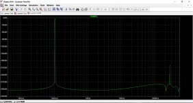
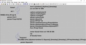
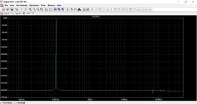
To try and get a handle on all this I picked an arbitrary frequency of 102753Hz that I wish to display for 25 cycles and to then display the FFT.
Using the 'longhand' method and opening Windows calculator it takes just a few seconds to calculate that the simulation run time needs to be:
2.433018987280176734499236032038e-4 seconds.
To set the timestep we just divide the above by 262144 (if we are using that value in the FFT) and get 9.2812308779913968448609772950668e-10
I'm using Windows calculator and so its easy to copy and paste the data directly into the sim.
I also tried to make sense of these commands by lifting some of this from other sims I have found on this site. This shows the FFT of the same signal using the other method.
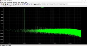
Last shot is the longhand method but with increased precision using the .options numdgt=7 command.
To try and get a handle on all this I picked an arbitrary frequency of 102753Hz that I wish to display for 25 cycles and to then display the FFT.
Using the 'longhand' method and opening Windows calculator it takes just a few seconds to calculate that the simulation run time needs to be:
2.433018987280176734499236032038e-4 seconds.
To set the timestep we just divide the above by 262144 (if we are using that value in the FFT) and get 9.2812308779913968448609772950668e-10
I'm using Windows calculator and so its easy to copy and paste the data directly into the sim.
I also tried to make sense of these commands by lifting some of this from other sims I have found on this site. This shows the FFT of the same signal using the other method.
Last shot is the longhand method but with increased precision using the .options numdgt=7 command.
Attachments
I've found the latest discussions quite interesting, and I'll admit my knowledge of applying many of these commands is very lacking, although the installed user manual gives a good description of many of them.
Hi Mooly,
A couple of things, it seems the desktop calculator uses an extended numerical representation since 64 bit IEEE floats (which SPICE uses) have at most 17 digit precision of the mantissa. Secondly your last plot seems to some kind of smoothing, just curious as to where that comes from an FFT of the output of the FPU's sin function has a noisy floor. IME sin(x) is identical across all computers and software packages to 15 digits (except of course special purpose ones).
Using the 'longhand' method and opening Windows calculator it takes just a few seconds to calculate that the simulation run time needs to be:
2.433018987280176734499236032038e-4 seconds.
Why bother, LTspice is perfectly capable of doing the math (to it's own limitations, lengths or precision [as Scott noted]).
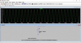
Mooly, you need to have an actual circuit in simulation to get valid results. The integrator behavior will change completely once there is actually something to simulate.
Secondly your last plot seems to some kind of smoothing, just curious as to where that comes from an FFT of the output of the FPU's sin function has a noisy floor. IME sin(x) is identical across all computers and software packages to 15 digits (except of course special purpose ones).
I've no answer to that. The only difference between the last plot and the second plot is the addition of numdgt=7 option which sets LT to double digit precision.
Why bother, LTspice is perfectly capable of doing the math (to it's own limitations, lengths or precision [as Scott noted]).
Yes, I realise that 🙂 I think my own limitations are part of the problem here, at least when anything involving mathematical concepts is concerned.
Mooly, you need to have an actual circuit in simulation to get valid results. The integrator behavior will change completely once there is actually something to simulate.
Thanks, that's actually sort of next on the list because I realise that when we are talking of a base level of -150db, -200db and particularly -300db we are down at the kind of levels you might get trying to pick up Voyager 😀
I've no answer to that. The only difference between the last plot and the second plot is the addition of numdgt=7 option which sets LT to double digit precision.
For information on 'Double-precision floating-point' look here 🙂
Double-precision floating-point format - Wikipedia
Yes, I realise that 🙂 I think my own limitations are part of the problem here, at least when anything involving mathematical concepts is concerned.
There may be more to consider (and I am not sure that LTspice is doing this [but it might]), that is 're-ordering' this may be done for higher speed and/or for better precision, when applied it will make manual comparisons almost impossible.
An Analysis of Reordering Algorithms to Reduce the Computational Cost of the Jacobi-Preconditioned CG Solver Using High-Precision Arithmetic | SpringerLink
Kahan summation algorithm - Wikipedia
Thanks, that's actually sort of next on the list because I realise that when we are talking of a base level of -150db, -200db and particularly -300db we are down at the kind of levels you might get trying to pick up Voyager 😀
Yes [keantoken] is totally right 🙂
Also:
From: https://wiki.scinet.utoronto.ca/wiki/images/f/f2/FP_Consistency.pdf
This [type of things/events] may [possibly], among others, occur even when no intentional/explicit re-ordering takes place.
Floating Point Contractions
This refers primarily to the generation of fused multiply-add (FMA) instructions on
the IA-64 architecture, which is enabled by default. The compiler may generate a
single FMA instruction for a combined multiply and add operation, e.g. a = b*c + d.
This leads to faster, slightly more accurate calculations, but results may differ in the
last bit from separate multiply and add instructions.
Floating point contractions may be disabled by one of the following:
/fp:strict (-fp-model strict)
#pragma float_control(fma,off)
/Qfma- (-no-fma) (this overrides the /fp or –fp-model setting)
When disabled, the compiler must generate separate multiply and add instructions,
with rounding of the intermediate result
From: https://wiki.scinet.utoronto.ca/wiki/images/f/f2/FP_Consistency.pdf
This [type of things/events] may [possibly], among others, occur even when no intentional/explicit re-ordering takes place.
Last edited:
- Home
- Design & Build
- Software Tools
- Installing and using LTspice IV (now including LTXVII), From beginner to advanced