For a symmetric "triangle", the value of d (duty cycle) = 0.5. For a positive ramp d= ~0.99 ( near to 1.0).


Question: I want to take the division of two voltages in a circuit and pass that through another circuit.
How do I do that? Since the values of the two voltages are only available after the run, a .param doesn't work.
Any ideas?
Jan
How do I do that? Since the values of the two voltages are only available after the run, a .param doesn't work.
Any ideas?
Jan
See whether the help file suggests that LTSPICE's "Behavioral" sources can make Vout = VinA / (VinB + 1E-11)
Mark, I tried a BS with V=V(a)/V(b), it did run (very slow) but the values don't plot they are NAN.
From the description it seems it only supports V(a)-V(b) but no division.
I wonder if a BS is dynamic, i.e. whether there is instantaneous feedback during a run or wheter it is resolved at start of run only.
Jan
From the description it seems it only supports V(a)-V(b) but no division.
I wonder if a BS is dynamic, i.e. whether there is instantaneous feedback during a run or wheter it is resolved at start of run only.
Jan
We're speaking of time-domain sim? Behavioral Source works fine for me. The denominator must not be (close to) zero, of course.Mark, I tried a BS with V=V(a)/V(b), it did run (very slow) but the values don't plot they are NAN.
From the description it seems it only supports V(a)-V(b) but no division.
I wonder if a BS is dynamic, i.e. whether there is instantaneous feedback during a run or wheter it is resolved at start of run only.
Frequency domain gets trickier as DC offsets of the AC sources start to a play role I haven't yet figured out exactly....
I accidentally created a "fun little homework problem" for myself, which other Forum members might possibly enjoy too.
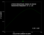
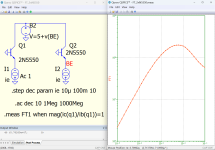
PROBLEM: Command LTSPICE to make a plot of the transition frequency "fT" (i.e. the frequency at which beta falls to 1.0) for the 2N5550 bipolar transistor, whose .MODEL is presupplied in LTSPICE. Plot fT versus collector current, all data measured at VCE = 5 volts and room temperature.
It flummoxed and perplexed me for quite some time, but eventually I got an output (on the fourth try!) that suits my needs: attached below. I used LTSPICE 24.0.12 if that matters.
Hope you enjoy!
_
Attachments
Very nice @bordodynov ! Your behavioral source B2 which sets the collector voltage as a function of the emitter voltage, is a beautiful touch. Congratulations.
Curly Braces and error logs when using Ian Hegglun's MOSFET models.
Where to start... I've been trying to rationalise the libraries in LT24 which will be a different topic to this but I've come up against the following 'error' that happens when I incorporate Ian Heggluns FET models into any simulation This is explained below. Everything works but its just an annoyance and something that bugs me.
Quick read version...
My spice output log is full of, well these... questionable use of curly braces:

Keeping this really simple to try and get a handle on this I swap the MOSFET library file in the 'cmp' folder for one with just a single model in it:

So when I go to choose a MOSFET I only see one model:

When I run the sim (which works just fine) that one model throws up all these errors. So you can imagine how long the list is with a dozen or more similar models:

Now it gets weird. If I replace the curly braces with normal ( and ) the sim still runs but the error log still says there is a curly braces problem. More experimentation shows the model only need be included in a sim and not even called into use for the errors to appear.
So the question is can these models be altered/rewritten in some way to stop this.
To simplify this even more here is a sim with the FET removed and the model details pasted on the sim. This should still give you the error in the Spice output log.
Note... this model included on the sim has had all the curly braces replaced by normal ( ) and yet it still triggers the same error.
For reference this is one of Ian's models in original form with the curly braces (which I removed in the sim version):
So when I run the attached file, this is what I still see even though no curly braces are present:


Where to start... I've been trying to rationalise the libraries in LT24 which will be a different topic to this but I've come up against the following 'error' that happens when I incorporate Ian Heggluns FET models into any simulation This is explained below. Everything works but its just an annoyance and something that bugs me.
Quick read version...
My spice output log is full of, well these... questionable use of curly braces:
Keeping this really simple to try and get a handle on this I swap the MOSFET library file in the 'cmp' folder for one with just a single model in it:
So when I go to choose a MOSFET I only see one model:
When I run the sim (which works just fine) that one model throws up all these errors. So you can imagine how long the list is with a dozen or more similar models:
Now it gets weird. If I replace the curly braces with normal ( and ) the sim still runs but the error log still says there is a curly braces problem. More experimentation shows the model only need be included in a sim and not even called into use for the errors to appear.
So the question is can these models be altered/rewritten in some way to stop this.
To simplify this even more here is a sim with the FET removed and the model details pasted on the sim. This should still give you the error in the Spice output log.
Note... this model included on the sim has had all the curly braces replaced by normal ( ) and yet it still triggers the same error.
For reference this is one of Ian's models in original form with the curly braces (which I removed in the sim version):
Code:
*VDMOS with subthreshold (c) Ian Hegglun Aug 2015
.model IRF640-25C VDMOS (Rg=5 Vto={4.30-6m*0} Lambda=3m
+ Rs={35m*(1+3.5m*0)} Kp={13.0/(1+8.8m*0)}
+ Ksubthres={0.23*(1+4m*0)} Mtriode={0.35} Rd={0.1*(1+5m*0)}
+ Cgdmax=2600p Cgdmin=10p a=0.35 Cgs=1250p Cjo=3000p
+ m=0.75 VJ=5 IS=1n N=1.3 Rb=0.01 )
So when I run the attached file, this is what I still see even though no curly braces are present:
Attachments
A bit of a discovery. Re writing the model by removing possibly unnecessary brackets removes all the errors but for one. The error log now shows a single { } (curly brace) error but all that is in the model code is a single pair of ( )
If I remove that pair there are no errors... but does the model still give the same results... one for tomorrow is that. Mathematically does it look right or not in that line? * 0 (multiply by zero) gives zero so I'm obviously missing how this is constructed somewhere. There are lines below this problem one with brackets such as Ksubthres=0.23*(1+4m*0) which are not an issue.

If I remove that pair there are no errors... but does the model still give the same results... one for tomorrow is that. Mathematically does it look right or not in that line? * 0 (multiply by zero) gives zero so I'm obviously missing how this is constructed somewhere. There are lines below this problem one with brackets such as Ksubthres=0.23*(1+4m*0) which are not an issue.
Hi Mooly,
I assume you are not using LT-IV anymore and have a later version. You can stop these curly brace errors by using the later mos model library for LT-XVII eg from the bordodynov site here http://bordodynov.ltwiki.org/standard.mos.XVII.txt
These curly brace errors are a legacy from LT-IV. Mike Engelhardt updated the VDMOS code with additional temperature parameters so curly braces are not used in the updated MOSFET models. The new parameters for temperature are "Bex" and "vtotc".
My apology for the concern and your time involved.
For those using LT-IV models see this post https://www.diyaudio.com/community/threads/better-power-mosfet-models-in-ltspice.266655/post-6280444
"To get correct temp operation at say 75C use the hard-wired models below (but don't use the Temp=<x> appendage to the part name):"
Thanks so much for that Ian 🙂 and for explaining what had happened. Definitely no apologies needed.
Thanks again.
Thanks again.
I tried a BVMark, I tried a BS with V=V(a)/V(b), it did run (very slow) but the values don't plot they are NAN.
From the description it seems it only supports V(a)-V(b) but no division.
I wonder if a BS is dynamic, i.e. whether there is instantaneous feedback during a run or wheter it is resolved at start of run only.
With V=V(a) it works as expected. As well with V=10*V(b).
With V=V(a)/V(b) it does something weird to me.
On a circuit where the voltage at a is 2.5V and the voltage at b is 30V.....I got 83.333mV ( instead of 83.333 )
Are you sure you want the ratio of two voltages ? This has no unit. May be, LTspice wants a physics unit.
I am using an old version, mileage might differ.
Last edited:
I have troubles with some circuits simulations that "Failed to find operating point". It occurs more often in AC analysis than on transient.
Fiddling with componant values, it occurs more or less. I think it has to do with stability, that is ennoying because the reason for these simulations is to know stability phase and gain margins.
What are the tricks to help at finding the operating point ?
Fiddling with componant values, it occurs more or less. I think it has to do with stability, that is ennoying because the reason for these simulations is to know stability phase and gain margins.
What are the tricks to help at finding the operating point ?
Last edited:
Operating point is the DC conditions - perhaps the circuit is ill-conditioned and has zero, or multiple or an infinity of DC solutions? An ac-analysis as I understand it first computes the dc operating points of every active device, then does a small-signal (i.e. linear) analysis using the operating points to determine gains/impedances of the devices.
This may be from multiple DC solution, but wierd because: About the same circuit but with slightly different res or cap values sometimes it finds, sometimes it does not. When it does find, it is as expected, by hand I can only see a unique solution.
The circuit is not involved at all: A PSU regulator for 400mA 30V output using 12 composnants.
A CCS ( 2 npn bjt + 2 res ) a CFP ( 1 npn bjt + 1 pnp bjt + 1 res ) a TL431 a divider ( 2 res + 1 cap ) a cap + res ESR. Then a load (1 res + 1 voltage PULSE ).
I thought LTspice had alternative strategies to find the DC operating point. I did not find those. May be well hidden or seen in another Spice ?
- Home
- Design & Build
- Software Tools
- Installing and using LTspice IV (now including LTXVII), From beginner to advanced


