I checked the Mosfet in Help and
Looks like the area scale factor is "M=..." which is case sensitive?
But I haven't checked a sim to see if "m=0.2" does the same as "M=0.2" when used after the model name in the VDMOS model.
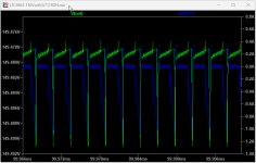
Re: no load in my sims - was to see if it reached steady state sooner, but it didn't, so I limited the test to 10ms rather than wait many minutes to get to 100ms.
There may be some way to get to 100ms (steady state) faster. Maybe some can suggest how, other than using a supercomputer.
I never noticed this before " [M=<area>] [m=<value>]" 2 options!M. MOSFET Vertical double diffused power MOSFET:
Syntax: Mxxx Nd Ng Ns <model> [L=<len>] [W=<width>] [M=<area>] [m=<value>] [off] [IC=<Vds, Vgs, Vbs>] [temp=<T>]
Looks like the area scale factor is "M=..." which is case sensitive?
But I haven't checked a sim to see if "m=0.2" does the same as "M=0.2" when used after the model name in the VDMOS model.
Re: no load in my sims - was to see if it reached steady state sooner, but it didn't, so I limited the test to 10ms rather than wait many minutes to get to 100ms.
There may be some way to get to 100ms (steady state) faster. Maybe some can suggest how, other than using a supercomputer.
Last edited:
I got that information from here: How to use the "m" parameter with MOSFETs. if you haven't seen it already.
The Si7113DN simulation runs quite a bit faster in v24 even in the VM I'm running it in. On v24 the Si7119DN simulation stalls after a few microseconds and finally produces a "Time step too small error".
I have the information I need from the simulations anyway - confirming that the specified components are up to the task with power and voltage estimates.
Thanks again for your help.
Did anyone else notice that D1 is a 60V diode operating under 150+24=174V. I suspect LTSpice ignores diode breakdown voltages, but a real diode would certainly limit the voltage to the avalanche voltage.
And the values used for R3+R5 are suspect given that the application note uses 500K for 5V, 10uA for this network. I know high value resistors are hard to find but I think R5 should be at least 10Meg, if not 15Meg. "It is recommended to set RFB2 to be greater than 8K, ..." ie 10K is near the limit. If you can't find resistors greater than 2Meg, a composite divider could be made of smaller resistors.
Finally, 47uF is a big cap at 150VDC. Initially, simulating with 47uF is a waste of time, until all other issues are clear.
The MBRS360 was the closest built-in diode I could find. The datasheet specifies a 200V one. I'll see if I can find a suitable model I can use.
Thanks for the advice on R3 and R5. I'll re-read that section of the datasheet. I did notice that 10.7M was close to the limit.
I'll take a close look at the output capacitor requirements too.
Thanks for the advice on R3 and R5. I'll re-read that section of the datasheet. I did notice that 10.7M was close to the limit.
I'll take a close look at the output capacitor requirements too.
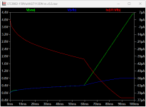
The inflection in the output voltage occurs where "the SS pin voltage is greater than the internal 0.8V reference, the VFB pin voltage regulates to the 0.8V internal reference".
Current from the Vfb peaks at 75uA when the output hits the programed -150V. The datasheet says it needs to be < 200uA so no problem there.
The Si7119DN model won't go past 84us on v17.1.11 or V24. Worked fine on V17.1.11 last evening and I haven't made any changes to it.
Current from the Vfb peaks at 75uA when the output hits the programed -150V. The datasheet says it needs to be < 200uA so no problem there.
The Si7119DN model won't go past 84us on v17.1.11 or V24. Worked fine on V17.1.11 last evening and I haven't made any changes to it.
Attachments
Last edited:
Hello,
It's been a while and I'm back on doing a sim run again as a review of my older amp circuits. Problem though was, why am I having 'time step too small error' surprisingly I had to repeatedly do a sim run again (maybe two to four times) and the error goes away. Was it a glitch for this newer version or do I have to update some spice directives? I have attached here the spice directives that I was using. I've been using this since the time of LTSpice IV.
My system was a 12th gen intel core i5 on an 8gb of ram.
Attachments
According to this video, the problem is probably the lack of a ground reference in the circuit. Spice voltages must be taken with respect to ground, zero volts. so, you cannot simulate a floating circuit. That includes all sides of a transformer circuit. You may have to add a high value resistance to ground.
Hi there all.
Because I am not very good with some things concern LTspice, I have a question about
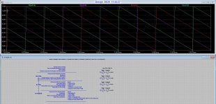
how to change the triangle to a sawtooth.
Dit change the dutycycl from 0.5 to 0.1 did make a sawtooth who was inverted. but
invert back when use the second dutycycl and change the first back.
Sawtoo is needed for ripple supression. Now i use the trianglewith 90 degree shifts
these shifts need to be stay there.
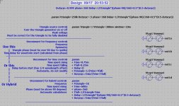
.param Ftriangle=250k Dutycyc=.5 phase=360 Delay=1/Ftriangle*((phase-90)/360+0.5*(0.5-dutycyc))
I am thankfull if someone can explain for me or show me.
regards
Attachments
Why not just set up a PWL source to your specs? Start at zero, go to some point at some lvel, then to another point closer by back to zero etc.
Just like you would draw it on mm paper.
Jan
Just like you would draw it on mm paper.
Jan
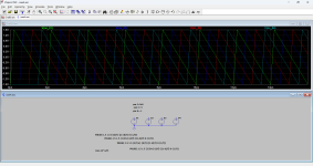
I need to setup four sawtooth signals where I can set the delay,s
Like in the pic, I had these setup also from a fellow here for use .
I am bad with LTspice concern the calculations.
Like in the pic, I had these setup also from a fellow here for use .
I am bad with LTspice concern the calculations.
This is not an LTspice problem. You must define the sawtooth yourself, on paper, start at time 0, next point is time 5 amplitude 10, next point is time 2 amplitude 0. That is one period.
Then place a voltage source on the schematic, open the menu for it (right click) and select PWL and fill in the points you just wrote down. Check how it looks and modify as needed.
Jan
Then place a voltage source on the schematic, open the menu for it (right click) and select PWL and fill in the points you just wrote down. Check how it looks and modify as needed.
Jan
You can also make a 'natural' swtooth with an ac source, rectifiers into an elco with a load resistor.
Get a nice sawtooth on the electrolytic just like the real thing ;-).
Jan
Get a nice sawtooth on the electrolytic just like the real thing ;-).
Jan
Still I can then not adjust the fase between them, now I have four voltage sources who can be setup for fase, like 90 degree
then 180, 270, degree etc as you see in the pc, see the asc. It is some more complicated then a single triangle or sawtooth,
this I can do, but for shifted signals I can not do it right, just do not now.
then 180, 270, degree etc as you see in the pc, see the asc. It is some more complicated then a single triangle or sawtooth,
this I can do, but for shifted signals I can not do it right, just do not now.
Attachments
It is always hard to work with someone else's construction, at least for me.
As I mentioned, I would just take 4 sets of 50Hz sine wave, rectifier, capacitor, load, to get a realistic wave to check PSRR, not an artificial one with a different spectrum.
You can set the phase for each sine wave to get different phases for the sawtooth.
Don't waste your time figuring someone else's stuff and still not have a realistic sawtooth.
Jan
Hi Steveu, it do look like I need, however the sawtooth needs to go from 0 to max in period the other way around.
I have done this on the asc I have use for triangles.
The only thing I did was change this.
.param Ftriangle=500k Dutycyc=.5 phase=360 Delay=1/Ftriangle*((phase-90)/360+0.5*(0.5-dutycyc))
to this, but is not a perfect sawtooth, but maybe risetime is to low I mean, inverted was risetime...
.param Ftriangle=500k Dutycyc=.01 phase=360 Delay=1/Ftriangle*((phase-90)/360+0.01*(0.01-dutycyc))
Attachments
If I do change the file like this.
.param Ftriangle=500k Dutycyc=0.99 phase=360 Delay=1/Ftriangle*((phase-90)/360+0.01*(0.99-dutycyc))
I get the sawtooth reversed and is what I need, but why it does not work if I use 1 and not 0.99 for both changes.
because when I do I get a more triangle/sawtooth mix waveform again but
.param Ftriangle=500k Dutycyc=0.99 phase=360 Delay=1/Ftriangle*((phase-90)/360+0.01*(0.99-dutycyc))
I get the sawtooth reversed and is what I need, but why it does not work if I use 1 and not 0.99 for both changes.
because when I do I get a more triangle/sawtooth mix waveform again but
Is there a way to make this a nice symmetrical one?Is this what you are looking for?
Aka shift the "duty cycle"
The end of the equation is always zero, so that does look wrong.
0.01*(0.99-dutycyc)) is zero for dutycyc = 0.99
Same for 0.5*(0.5-dutycyc)) for dutycyc = 0.5
It is anyway confusing that in some cases you use the Dutycyc variable and in some cases the actual value.
That invites errors. If you set dutycyc to 0.9, then use (1-dutycyc) instead of 0.1, much less chance that you forget something when you change the duty cycle.
Jan
Last edited:
- Home
- Design & Build
- Software Tools
- Installing and using LTspice IV (now including LTXVII), From beginner to advanced

