Does anyone have any info on the (latest) LTspice .asc file format, or even some program code to read/manipulate it? It looks easy enough, it appears some people have done it or at least partially done it, but not publicly documented it. LTspice model files appear well documented. I found some general SPICE documentation (https://www.egr.msu.edu/classes/ece445/mason/Files/KSU_short_spice_tutorial.pdf) but not specifically for LTspice.
What I want to do is replace values in array of resistors with a list of values (from a spreadsheet or text file). Here's part of my .asc file of two resistors:
It'll be easy enough to look for "SYMATTR InstName R<n>" and then "SYMATTR Value " on the next line, and write that line [to a new file, then rename files when done] with the new value for R<n> for n different values. This would be much easier and faster than changing each resistor value in the schematic editor (what I've been doing, for 12 or more resistors). So unless there's something out there, I'm going to write something to do that.
I really don't need to know what all these keywords are or do, though it would be nice to document this.
What I want to do is replace values in array of resistors with a list of values (from a spreadsheet or text file). Here's part of my .asc file of two resistors:
Code:
SYMBOL res -224 192 R180
WINDOW 0 36 76 Left 2
WINDOW 3 36 40 Left 2
SYMATTR InstName R1
SYMATTR Value 330
SYMBOL res -128 208 R180
WINDOW 0 36 76 Left 2
WINDOW 3 36 40 Left 2
SYMATTR InstName R2
SYMATTR Value 560I really don't need to know what all these keywords are or do, though it would be nice to document this.
Not sure what your problem is. The 3 methods for using 3rd party bjt models that I use are:Hello everyone, I thank the owner of the topic for the information, but I have this question: what should I do for the 2sc5200 model, for example, to feel here. I tried several ways to copy the cordel.txt file but without success.
View attachment 1160158
1. Use .op to add ".lib D:\SPICE\lib\Cordell-Models.txt" to the schematic that points to the 2SC5200 model,
including files on the web like ".lib http://www.minek.com/lib/minek.lib". You have to change "NPN" on the schematic to "2SC5200".
2. Use .op to add ".mod NPN 2SC5200 ....." to the schematic. You have to change "NPN" on the schematic to "2SC5200".
3. Add ".mod NPN 2SC5200 ..." to the "standard.bjt" file. This is the only method that makes 2SC5200 available in the select new part list.
Last edited:
So......
I accidently clicked something and generated a .IMP file (presumably impedance) and I've no idea what I did to generate this. I was doodling with a sim of the ACA amp and looking at FFT's. This is what appeared. You can see I am on the output node.
I'll attach the .IMP file in a zipped folder. It will open in LT if you browse for the file using LT and set the options in the dropdown to 'all file types' to make it visible. The file does not auto delete which is how I found it this morning (I have .raw, .net etc to delete on closing)


I will also attach the ACA file if anyone cares to try and recreate it. Should click and run with default models.
I accidently clicked something and generated a .IMP file (presumably impedance) and I've no idea what I did to generate this. I was doodling with a sim of the ACA amp and looking at FFT's. This is what appeared. You can see I am on the output node.
I'll attach the .IMP file in a zipped folder. It will open in LT if you browse for the file using LT and set the options in the dropdown to 'all file types' to make it visible. The file does not auto delete which is how I found it this morning (I have .raw, .net etc to delete on closing)
I will also attach the ACA file if anyone cares to try and recreate it. Should click and run with default models.
Attachments
Seems the .imp file is a impulse response file that is generated by running a FFT on the FFT waveform.
I found the info at the ltspice usergroup - https://groups.io/g/LTspice/topic/99912388
I found the info at the ltspice usergroup - https://groups.io/g/LTspice/topic/99912388

One method I used is to pull up the BOM and change a bunch of values there. They will automagically be reflected in the schematic and netlist.Does anyone have any info on the (latest) LTspice .asc file format, or even some program code to read/manipulate it? It looks easy enough, it appears some people have done it or at least partially done it, but not publicly documented it. LTspice model files appear well documented. I found some general SPICE documentation (https://www.egr.msu.edu/classes/ece445/mason/Files/KSU_short_spice_tutorial.pdf) but not specifically for LTspice.
What I want to do is replace values in array of resistors with a list of values (from a spreadsheet or text file). Here's part of my .asc file of two resistors:
It'll be easy enough to look for "SYMATTR InstName R<n>" and then "SYMATTR Value " on the next line, and write that line [to a new file, then rename files when done] with the new value for R<n> for n different values. This would be much easier and faster than changing each resistor value in the schematic editor (what I've been doing, for 12 or more resistors). So unless there's something out there, I'm going to write something to do that.Code:SYMBOL res -224 192 R180 WINDOW 0 36 76 Left 2 WINDOW 3 36 40 Left 2 SYMATTR InstName R1 SYMATTR Value 330 SYMBOL res -128 208 R180 WINDOW 0 36 76 Left 2 WINDOW 3 36 40 Left 2 SYMATTR InstName R2 SYMATTR Value 560
I really don't need to know what all these keywords are or do, though it would be nice to document this.
Depending on how many values you need to change, may be a fast track.
Jan
Oh well done 🙂 you've nailed it with that.Seems the .imp file is a impulse response file that is generated by running a FFT on the FFT waveform.
I found the info at the ltspice usergroup - https://groups.io/g/LTspice/topic/99912388
I can see what I must have done now, I ran the FFT and reduced the "Number of Data Points Samples in Time" from the default 262144 to something lower like 32768 to get the detail I wanted. From there I must have lost concentration and run the FFT again, as you say on the FFT just done, but now with a much higher sample point setting. That gives some weird results and creates the IMP file which by the way seems non searchable to locate, at least in an easy way.
Thanks.
Hi There
I have use always the K1 l1 l2 ETC 0.98,0.99 Statements.
But I saw these coming by and looks nice to calc also inductions and windings.
LLC test sim with feedback.. 6.3, 12.6, 350, 2x120 volts. 350 and 120 is low amperage for tube hybrid, other are filament voltages (now) stacked windings and
feedback. Here I do use normal K statements. I always did by the way. using 0.98 coupling.
regards
Recently I stumbled across a side issue, which turned out to be a delightful little "homework problem" in the application of LTSPICE.
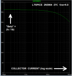
I don't know about you, but I found it difficult to invent strategies that would put collector current on the horizontal axis. A mental blind spot. Eventually I (think I) succeeded as shown below.
Fool around with it and have some fun! It's not an IQ test, it's just a happy little LTSPICE puzzle. A brain teaser.
BTW it can be done with the TI-TINA simulator too. But this is an LTSPICE thread.
_
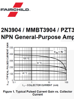
Problem: Use LTSPICE to reproduce the middle (room temperature) trace in Figure 1 of the 2N3904 datasheet. Namely, have LTSPICE plot "Beta" (Icollector / Ibase) versus collector current, for a 2N3904 at room temperature and Vce = constant 5.00 volts. Beta should be on the vertical axis with a linear scale, and Icollector should be on the horizontal axis with a log scale.
I don't know about you, but I found it difficult to invent strategies that would put collector current on the horizontal axis. A mental blind spot. Eventually I (think I) succeeded as shown below.
Fool around with it and have some fun! It's not an IQ test, it's just a happy little LTSPICE puzzle. A brain teaser.
BTW it can be done with the TI-TINA simulator too. But this is an LTSPICE thread.
_
Attachments
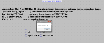
Youv'e defined Lp as 20m then again in a formula that refers back to the original definition.Hi All
I did try to setup a sim for transformer as in this pic, seen on internet.
I get a error, so can someone help me out what I did wrong.
thnks.
Lp cannot be both a reference designator and its value. Sorry if I don't try to make sense of the rest of it.Hi All
I did try to setup a sim for transformer as in this pic, seen on internet.
I get a error, so can someone help me out what I did wrong.
thnks.
Hi Everyone,
Is there a chance to share the LTspice model of LMG1205? I want to simulate it in LTspice.
Is there a chance to share the LTspice model of LMG1205? I want to simulate it in LTspice.
I have this from wiki, but has little info. I did it a other way do work fine.Lp cannot be both a reference designator and its value. Sorry if I don't try to make sense of the rest of it.
Hi all guys and womans.
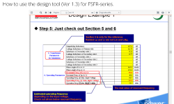
I have a question about simulating LLC converters, I have succes but have a question about the calculator, the picture states that the transformer
in section 5 are for simulation, but how do I put this into LTspice, I have use Lp and Lr and have later include the leakage inductance into Lr so I can make
transformer K =1. I have a formula who can calculate leakage with secondary winding shorted K=√(1-(Lshort/Lp). and use this in LTspice and left the Lp as calculated. I presume that LTspice do handle this K as leakage inductance?
Little bit complicated. I can simulate and have locking feedback in reach of 50 mA to 10 amp with M =8 Q = 0.29.
Thanks in advance.
Attachments
Celebrating my beloved LTspiceIV, 10.96 years without updating ;-)

Greetings all,
before I start reading the monstrous 3,000+ post thread, I was wondering if the following was discussed or someone knows how to do it.
I have a measurement of a driver impedance in terms of frequency, magnitude and phase. I have read that the data can be entered into a "frequency table" and associated with a symbol in a schematics.
However, I cannot find any (preferably detailed) description how to do so. Any advice in this regard would be appreciated.
Kindest regards,
M
- Home
- Design & Build
- Software Tools
- Installing and using LTspice IV (now including LTXVII), From beginner to advanced