Hi everyone,
Does anybody know if there is a way to extract a list of component names and values from an. asc file?
Example, if one wanted to make a BOM without combing through the schematic. Do you know if there a way to do this?
Thanks,
Tim
Does anybody know if there is a way to extract a list of component names and values from an. asc file?
Example, if one wanted to make a BOM without combing through the schematic. Do you know if there a way to do this?
Thanks,
Tim
helitim, Try this:Look at the netlist, it's all there.
Tools|Export netlist, or
View|Spice Netlist
Jan
Copy netlist to spreadsheet. EG OpenOffice when you Paste the netlist the filter dialog appears, select space delimiter, OK. Then Sort (in Data menu) by 1st column. Then delete the second and third columns (they are nodes) leaving name then value. Clear unwanted rows. That's it
.
Attachments

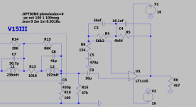
Would anyone enlight me on a problem?
I tried to sim a phono circuit based on an op-amp from LTspice archive, LT1115 and the simulation works no matter what the input bias resistor value is showing identical results even with no DC bias at all...Can someone explain this matter to me or if there are other op-amps that can deal with this condition in a different manner or if i need some convergence rule i don't know, or what do i need to know and do to figure out the effect of a given value resistor biasing the inputs ?
I tried to sim a phono circuit based on an op-amp from LTspice archive, LT1115 and the simulation works no matter what the input bias resistor value is showing identical results even with no DC bias at all...Can someone explain this matter to me or if there are other op-amps that can deal with this condition in a different manner or if i need some convergence rule i don't know, or what do i need to know and do to figure out the effect of a given value resistor biasing the inputs ?
Attachments
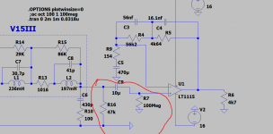
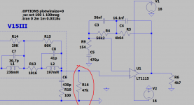
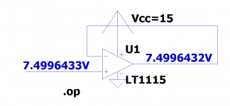
I suspect it is just because the opamp model is to close to ideal with no inherent offset or difference in offset between the two inputs. In other words it behaves more as an ideal theoretical part.
Would anyone enlight me on a problem?
I tried to sim a phono circuit based on an op-amp from LTspice archive, LT1115 and the simulation works no matter what the input bias resistor value is showing identical results even with no DC bias at all...Can someone explain this matter to me or if there are other op-amps that can deal with this condition in a different manner or if i need some convergence rule i don't know, or what do i need to know and do to figure out the effect of a given value resistor biasing the inputs ?
This is probably because you are using a very short sim time.
When the sim starts there is zero volt on your large input cap and it takes time to charge it with the input current from the amp.
Try the same with a much longer time window or a much smaller input cap and you will probably see that the DC voltage at the output starts drifting.
Hans
I am trying to set up a current source that will conduct a fixed current, plus a fraction of another (varying) current.
Like I1 = 10mA + 0.5*I2. How can I do that? The standard CS and VCCS don't accept anything else but a constant.
Jan
Like I1 = 10mA + 0.5*I2. How can I do that? The standard CS and VCCS don't accept anything else but a constant.
Jan
That is - troubling ... 😱
I can't remember that exchange at all.
Thanks for your patience,
Jan
I can't remember that exchange at all.
Thanks for your patience,
Jan
I thought about that too just wasn't sure, but i wanted to hear other's opinion.Do you know a bipolar low noise op-amp in ltspice library that doesn't have the same isssue, good enough to run some tests?The models include equal resistors between the input and power pins to simulate input currents.
I tried that and it's not the case.I lowered the input capacitor to the lowest possible value to pass 1khz witout significant level loss(10nf...100nf) and increased the sim time to 100m from 11ms, but i always put a start time at 1ms.I've repeated the tests at 10khz...same thing.This is probably because you are using a very short sim time.
When the sim starts there is zero volt on your large input cap and it takes time to charge it with the input current from the amp.
Try the same with a much longer time window or a much smaller input cap and you will probably see that the DC voltage at the output starts drifting.
Hans
There was also a 470uF cap on the other input. Did you try to lower (or delete) that too?
Jan
Jan
I know. I was referring to post 2669 from Hans. In that context, the 470uF has the same effect as the input cap he mentioned.
That 470uF takes time to charge.
Jan
That 470uF takes time to charge.
Jan
@Jan when you added (or delete) you reffered to offset.I tried that too, but strictly speaking it doesn't really matter..Problem was just partaially solved(regarding only to the offset problem) by using opa228 spice model as i am using real opa2228.For some reason they provide now the.lib file too.My real concerns aren't solved yet by the new model but at least needs external bias.
I don't know what you are reading, but I never referred to offset, I didn't even think about it.
I was just trying to be helpful.
But hey, whatever floats your boat!
Jan
I was just trying to be helpful.
But hey, whatever floats your boat!
Jan
Last edited:
Making progress in getting the 6HV5 up and running, but hit a snag.
After a lot of time roaming the ´net, I found an LTspice model for the 6HV5±
But when I try to run it, I get an error from the Bp which I assume is a behavioral source. The error is:
u1:bp: Unknown circuit node " nc_02" requested in behavioral source.
I have no idea where that nc_02 thing is ... Also, what means that ' uramp' ?
Anybody can help me out?
Jan
Plain text:
.subckt 6HV5  P G K
    Bp  P K  I=((0.002251977888m)+(-5.369015936e-005m)*V(G,K))*uramp((370.7812379)*V(G,K)+V(P,K)+(423.2938397))**1.5 * V(P,K)/(V(P,K)+(57.14378617))
.ends
After a lot of time roaming the ´net, I found an LTspice model for the 6HV5±
Code:
.subckt 6HV5 P G K
Bp P K I=((0.002251977888m)+(-5.369015936e-005m)*V(G,K))*uramp((370.7812379)*V(G,K)+V(P,K)+(423.2938397))**1.5 * V(P,K)/(V(P,K)+(57.14378617))
.endsBut when I try to run it, I get an error from the Bp which I assume is a behavioral source. The error is:
u1:bp: Unknown circuit node " nc_02" requested in behavioral source.
I have no idea where that nc_02 thing is ... Also, what means that ' uramp' ?
Anybody can help me out?
Jan
Plain text:
.subckt 6HV5 P G K
Bp P K I=((0.002251977888m)+(-5.369015936e-005m)*V(G,K))*uramp((370.7812379)*V(G,K)+V(P,K)+(423.2938397))**1.5 * V(P,K)/(V(P,K)+(57.14378617))
.ends
Last edited:
- Home
- Design & Build
- Software Tools
- Installing and using LTspice IV (now including LTXVII), From beginner to advanced