I see, quite a complex circuit!
I think it is extremely unlikely that the exact value of R8 has any impact on THD in a real circuit. You may see some sim artifacts/startup due to the large cap. Try putting another 100R between R8 and the base of Q3 to isolate it.
Jan
I think it is extremely unlikely that the exact value of R8 has any impact on THD in a real circuit. You may see some sim artifacts/startup due to the large cap. Try putting another 100R between R8 and the base of Q3 to isolate it.
Jan
Thank you Jan.
I already built the circuit with R8 set to 100 and it works wonderfully.
When I simulated it with 1kohm, THD was reduced and 3rd was very reduced but I do not know if it works in the real world... will need to build this ccs in a breadboard.
Will try your mod also.
Best
I already built the circuit with R8 set to 100 and it works wonderfully.
When I simulated it with 1kohm, THD was reduced and 3rd was very reduced but I do not know if it works in the real world... will need to build this ccs in a breadboard.
Will try your mod also.
Best
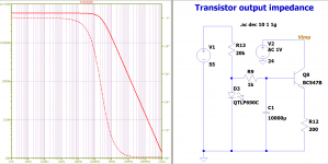
SeeI made this circuit but now I am reading the ccs load resistor impedance (2kohm).
Attachments
Thank you so much.
Yours is the best solution.
Glad I was able to help.
This is a "library" file containing a number of subcircuits, most of which have specialized purposes. The one that is relevant is the very first one in the file, labeled ".SUBCKT LMG1210." This is a rather complicated model, with 21 "pins," and like the LMG1205 model, some of these pins are duplicates that are connected together internally. In the physical pin-out diagram on page 3 of the datasheet (see link below), there are 3 pins plus a pad labeled HS, 4 pins labeled NC or NC1 (for no connection), and 2 pins plus a pad labeled VSS. So you could create a symbol that consolidates these duplicate pins into one each (and ignore the NC pins) so that you have a symbol that looks like the one shown in section 8.2 on page 16 of the datasheet, which has only 12 identified pins. This is what I did for the LMG1205 "alternate" symbol. Give this a try and see if you can make that work; it will be a good learning experience!
https://www.ti.com/lit/gpn/lmg1210
I have not succeed, I have to say that the LMG1205 dfo work, also with the part who has the auto made level does work normally.
I did connect these pins in schematic and simulation did work fine. For the LMG 1210 I did not see what is needed, not strange because I do design amps, I am not that good in LT spice model making/adjusting, it is a quite complicated program.
I did remove some pins so it look like the page 16 connection setup, but get the same error. I did read some models do not work well also. The LMG 1205 does work fine, with both alternate and auto symbols.
regards
Try the attached. I've included both an auto-generated symbol and one with the duplicate pins and non-connected pins hidden. You might want to try the auto-generated symbol first, and then the alternate one.
You can't delete the pins that you want hidden because that will cause a mismatch between the subcircuit pin order and the symbol. Their labels can be hidden if you don't want to see them but the pins themselves must remain part of the symbol file. Their squares will still be visible even though their text labels have been hidden.
I hope this helps.
Attachments
I had delete them from symbol not the model but that is mine fault then, I just have to hide them?
Oke I did try, get the same error, so I did oke I think but maybe a fault into the model. Did try the 1205 myself again, and that did work, to be shure.
regards
Oke I did try, get the same error, so I did oke I think but maybe a fault into the model. Did try the 1205 myself again, and that did work, to be shure.
regards
Attachments
Last edited:
It could be a problem with the model, or how it is used in your schematic (I couldn't see but a small part of the schematic in your screen shot).
Maybe the following link will help. It shows the use of the model in LTspice using the auto-generated symbol that I provided. I think you should try to get your schematic working with the auto-generated symbol before trying the alternate symbol (which should also work if the model is good).
https://e2e.ti.com/support/power-management/f/196/t/934704
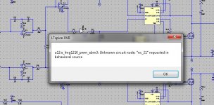
I have managed to let it work, but much errors in model.
Strange because people use it, however I have a class d who has symetrical voltages and not a ground for VSS because I do need reference from there for inputs. I do not now if this is possible at all with this chip. The lmg1205 does well.
The errors where because I had nothing connected.
I get this after sim, see pic.
regards
Attachments

Last edited:
here are the resulting simulations
Those ccs are directly proportional to the bias current. For bjts Rout=Va/Ic2 where Va is the constant Early voltage. So if your collector bias was decreased by half the out impedance doubles. Run your sim agian but step the bias to see this effect. ( hopefully your models have a proper Va, many Dont). Fets are similar.
I have managed to let it work, but much errors in model.
Strange because people use it, however I have a class d who has symetrical voltages and not a ground for VSS because I do need reference from there for inputs. I do not now if this is possible at all with this chip. The lmg1205 does well.
The errors where because I had nothing connected.
I get this after sim, see pic.
regards
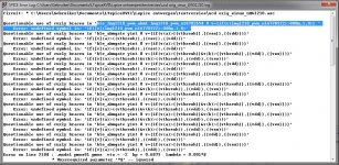
The model does work only the lower mosfet, and I get error about questionable error.
Here is somethibng about that, but that b$e where LTspice does complain about I can not found in wordpad looking at it.
https://e2e.ti.com/support/tools/sim-hw-system-design/f/234/t/646929
Here she mention remove these but I can't find them in normal tekst search in tekst editor see blue colored part, It is not in .lib, so maybe tekst fault, ansi or something?
What is happening here?
Attachments
Last edited:
Curly braces are typically used to denote parameters, and a look at the subcircuit shows that the curly brace is used in several places where ordinary parentheses probably should be used instead. Trying to find and correct all of these instances would be tedious and prone to human error. In any case, LTspice flags these as warnings, not errors, so the simulation should continue to run unless LTspice encounters some other error.
A Google search indicates that a number of LTspice users have encountered problems with the LMG1210 model, although the symptoms appear to be different depending on the specific schematic. I'm not familiar enough with this chip to troubleshoot its SPICE model so I'm not sure I can help much more. Maybe someone else who has run simulations with this device can weigh in.
A Google search indicates that a number of LTspice users have encountered problems with the LMG1210 model, although the symptoms appear to be different depending on the specific schematic. I'm not familiar enough with this chip to troubleshoot its SPICE model so I'm not sure I can help much more. Maybe someone else who has run simulations with this device can weigh in.
Open the model file with a text editor and make a mass substitution:
{{vdd}} --> vdd
{{vss}} --> vss
{{vthresh}} --> vthresh
Also make the substitution
lambda = 0.001*S -->lambda=10m
Other adjustments may be necessary, but the above are mandatory.
{{vdd}} --> vdd
{{vss}} --> vss
{{vthresh}} --> vthresh
Also make the substitution
lambda = 0.001*S -->lambda=10m
Other adjustments may be necessary, but the above are mandatory.
If you want to use this chip with negative power, you need to shift the control signal down.
You also need to power the VDD not to the common wire, but to the VSS. The simplest option is to use a zener and a resistor.
You also need to power the VDD not to the common wire, but to the VSS. The simplest option is to use a zener and a resistor.
Last edited:
Open the model file with a text editor and make a mass substitution:
{{vdd}} --> vdd
{{vss}} --> vss
{{vthresh}} --> vthresh
Also make the substitution
lambda = 0.001*S -->lambda=10m
Other adjustments may be necessary, but the above are mandatory.
I feel myself incredible stupid, I just did read the complains of LTspice wrong, I did discover that yesterday, but see that I am already be helped by you guys, really appreciated afcourse for the help.
@Bordodynov
I did VVS on the negative rail, I do try also what you did mention to tie the null of vdd to that. There is also a Vcc who maybe need that.
thanks all.
regards
Open the model file with a text editor and make a mass substitution:
{{vdd}} --> vdd
{{vss}} --> vss
{{vthresh}} --> vthresh
Also make the substitution
lambda = 0.001*S -->lambda=10m
Other adjustments may be necessary, but the above are mandatory.
Searching with search on a texteditor do not work well, only typing capital letters did work in some way but
managed it, oke the vss I did see have just one curly bracket and that is oke because remove it will give errors.
I have only edited lambda = 0.001*S -->lambda=10m twice and this did let remove the errors.
I get only lower fet switching not the upper one, so that need attention in schematic, like vdd vss ground uplift.
Thanks al.
Last edited:
Those ccs are directly proportional to the bias current. For bjts Rout=Va/Ic2 where Va is the constant Early voltage. So if your collector bias was decreased by half the out impedance doubles. Run your sim agian but step the bias to see this effect. ( hopefully your models have a proper Va, many Dont). Fets are similar.
Collector current is set with the emitter resistor.
To reduce collector current we increase emitter resistor and this increases impedance.
Am I reasoning correctly ?
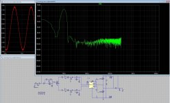
Using this simulation command:
.tran 0 45m 5m 0.01u
To get nice clean FFT results like this:
I am generating .raw files of 1.6gb !
Is there any way to instruct LTspice to delete this .raw file when the .raw window is closed to avoid the build up of vast amounts of data ?
Thanks in advance
mike
.tran 0 45m 5m 0.01u
To get nice clean FFT results like this:
An externally hosted image should be here but it was not working when we last tested it.
I am generating .raw files of 1.6gb !
Is there any way to instruct LTspice to delete this .raw file when the .raw window is closed to avoid the build up of vast amounts of data ?
Thanks in advance
mike
Tools=>Control Panel=>Operation, check the automatically delete .raw files option box.
That works most of the time. Sometimes it doesn't. I had this argument with Mike E a couple of times, he said impossible, it always works, end of story. I wonder if the new guy will fix it.
That works most of the time. Sometimes it doesn't. I had this argument with Mike E a couple of times, he said impossible, it always works, end of story. I wonder if the new guy will fix it.
Also remember that each new .raw file has the same name thus overwrites the previous one. So there's no buildup of data files.
Edit: I realize this is not the case if you run several different projects, they each each have their own ...
So better to auto-delete.
Jan
Edit: I realize this is not the case if you run several different projects, they each each have their own ...
So better to auto-delete.
Jan
Last edited:
- Home
- Design & Build
- Software Tools
- Installing and using LTspice IV (now including LTXVII), From beginner to advanced