Found one answer:
The function "uramp" is the integral of the unit step: for an input x, the value is zero if x is less than zero, or if x is greater than zero
the value is x. These two functions are useful in sythesizing piece-wise non-linear functions, though convergence may be adversely affected.
Jan
The function "uramp" is the integral of the unit step: for an input x, the value is zero if x is less than zero, or if x is greater than zero
the value is x. These two functions are useful in sythesizing piece-wise non-linear functions, though convergence may be adversely affected.
Jan
Need a bit more help please to bring this to an end. I have an extremely smart and knowledgeable friend who developed the parameters for a model for the 6HS5 tube for me.
Then he says: just enter them in the Koren tube model in LTspice. Huh?
I asked him again but he doesn't even get how ignorant I am here, and I don't want to press my luck.
So pretty please is there anyone here who can help me out? The model parameters and the equations are in the attached, but I have no idea how to turn that into a model.
Jan
Attachments
This works for me:
.subckt 6HV5 P G K
Bp P K I=((0.002251977888m)+(-5.369015936e-005m)*V(G,K))*uramp((370.7812379)*V(G,K)+V(P,K)+(423.2938397))**1.5 * V(P,K)/(V(P,K)+(57.14378617))
d3 G K dx1
CGK G K 19p
CPK P K 7p
CGP G P 1.5p
.model dx1 d(is=1n rs=2k cjo=1pf N=1.5 tt=1n)
.ends
.subckt 6HV5 P G K
Bp P K I=((0.002251977888m)+(-5.369015936e-005m)*V(G,K))*uramp((370.7812379)*V(G,K)+V(P,K)+(423.2938397))**1.5 * V(P,K)/(V(P,K)+(57.14378617))
d3 G K dx1
CGK G K 19p
CPK P K 7p
CGP G P 1.5p
.model dx1 d(is=1n rs=2k cjo=1pf N=1.5 tt=1n)
.ends
Attachments
Hmmm, yes, that works, after I had to correct a typo:
In the section: "... )+(4 23.2938397))**1.5 ... " the space between 4 and 23 throws a syntax error, taking out the space fixes it.
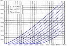
Do you know where this come from, how is it developed?
Mind you, I am grateful for the model, but I really would like to know how someone gets to something like that.
The attachment in # 2682 is developed from curve fitting by my friend, and I really would like to know how to turn it into a model.
I realize this is not an LTspice issue but a math issue ...
Jan
In the section: "... )+(4 23.2938397))**1.5 ... " the space between 4 and 23 throws a syntax error, taking out the space fixes it.
Do you know where this come from, how is it developed?
Mind you, I am grateful for the model, but I really would like to know how someone gets to something like that.
The attachment in # 2682 is developed from curve fitting by my friend, and I really would like to know how to turn it into a model.
I realize this is not an LTspice issue but a math issue ...
Jan
Last edited:
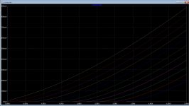
I'm not sure how that one was done. The following was done by eyeballing the Curves while varying the Koren parameters, look at the URL for details.
**** 6HS5******************************************
* Created on 03/28/2021 01:11 using paint_kit.jar 3.1
* Model Paint Tools: Trace Tube Parameters over Plate Curves, Interactively
* Plate Curves image file:
* Data source link:
*----------------------------------------------------------------------------------
.SUBCKT 6HS5 1 2 3 ; Plate Grid Cathode
+ PARAMS: CCG=22P CGP=1.8P CCP=11P RGI=2000
+ MU=343.4 KG1=66.93 KP=3966.4 KVB=1000 VCT=0.04248 EX=1.267
E1 7 0 VALUE={V(1,3)/KP*LOG(1+EXP(KP*(1/MU+(VCT+V(2,3))/SQRT(KVB+V(1,3)*V(1,3)))))}
RE1 7 0 1G ; TO AVOID FLOATING NODES
G1 1 3 VALUE={(PWR(V(7),EX)+PWRS(V(7),EX))/KG1}
RCP 1 3 1G ; TO AVOID FLOATING NODES
C1 2 3 {CCG} ; CATHODE-GRID
C2 2 1 {CGP} ; GRID=PLATE
C3 1 3 {CCP} ; CATHODE-PLATE
D3 5 3 DX ; POSITIVE GRID CURRENT
R1 2 5 {RGI} ; POSITIVE GRID CURRENT
.MODEL DX D(IS=1N RS=1 CJO=10PF TT=1N)
.ENDS
*$
Last edited:
I couldn't get your friends numbers to work properly, perhaps the underlying equation is a little different.
Yes it is pretty good, and it works nicely in my circuit.
And that is the purpose, the model is not a purpose in itself of course.
So I will go back into user mode - thanks guys for your help, hope I can return the favor at some point in the future!
Jan
And that is the purpose, the model is not a purpose in itself of course.
So I will go back into user mode - thanks guys for your help, hope I can return the favor at some point in the future!
Jan
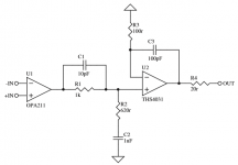
I came across this thread on Samuel Groner's Composite/Super Op-amp: Samuel Groner's super opamp
I would like to learn how to simulate and stabilize such a composite op-amp with LTspice. Since I just started to learn LTspice recently I was wondering if anyone had a good op-amp or even composite amp LTspice .asc file that they are willing to share? (To help me start this effort in the right direction.)
I am interesting in seeing what performance could be achieved with more standard operational amplifiers such as LM4562, OPA2134, AD823, etc.
Attachments
What's the consensus? Should I abandon LTspice IV?
This is on Windows 10...
I've been using LTspice IV only because I'm too lazy to go through upgrading and it's working fine for my limited purposes. It's been a long time, though. Is there a truly compelling feature or other reason to move up to LTspice XVII?
Thanks, and sorry if this is off-topic.
This is on Windows 10...
I've been using LTspice IV only because I'm too lazy to go through upgrading and it's working fine for my limited purposes. It's been a long time, though. Is there a truly compelling feature or other reason to move up to LTspice XVII?
Thanks, and sorry if this is off-topic.
I came across this thread on Samuel Groner's Composite/Super Op-amp: Samuel Groner's super opamp
I would like to learn how to simulate and stabilize such a composite op-amp with LTspice. Since I just started to learn LTspice recently I was wondering if anyone had a good op-amp or even composite amp LTspice .asc file that they are willing to share? (To help me start this effort in the right direction.)
I am interesting in seeing what performance could be achieved with more standard operational amplifiers such as LM4562, OPA2134, AD823, etc.
I think the start would be to read Samuel and Martin's article about it.
He admitted of not having been able to develop a closed procedure to calculate the compensation. For Samuel to say that, means we mere mortals have no chance ...
Jan
Last edited:
Here's the almost original.
Jan
Jan
Attachments
Last edited:
Hi Guys.
DO somebody know how to simulate a current transformer? I have one in class d as current feedback but when I do primairy set to 20 mH oscillation stops, when I do put it back to 1 mH it works again.
Maybe the leakage from such a transformer is quite high seen the winding through it, so 1 needs to 0.5 or such.
Thanks
regards
Attachments
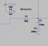
It,s current transformer so sense winding is primairy, resistor needs to be on secondairy was mine info from internet.
200n is primary and 20mH secondary, so I have simulate it.
But now it did work with change in components.
I get proper feedback and on 20 Khz it looks good. Afcourse need to build it to see what happens.
regards
200n is primary and 20mH secondary, so I have simulate it.
But now it did work with change in components.
I get proper feedback and on 20 Khz it looks good. Afcourse need to build it to see what happens.
regards
Attachments
How to add noise?
Hi,
I would like to simulate the effect of high frequency (> 50kHz) DSD quantisation noise on a grounded cathode amplifier stage in order to study intermodulation effects in the audio band.
What's the best way to add noise to the input signal?
One way that comes to mind is to add a summing op amp to the input and sum the noise and input signals that way.
Any other suggestions please?
You would need a really good model of the tube's nonlinearity curve. Spice is not a good tool if the distortion is very low. It might be easier to build a breadboard and test it. It would definitely be more accurate.
You would need a really good model of the tube's nonlinearity curve. Spice is not a good tool if the distortion is very low. It might be easier to build a breadboard and test it. It would definitely be more accurate.
Thanks Demian. We actually have a high end CD/SACD player/DAC that we suspect has no 50kHz filter on the output. It's output goes into a 4-way tube crossover. Each section is preceded by a 20dB gain stage.
We're getting loads of noise whenever playing SACDs or feeding DSD into the DAC.
I was hoping to build a simulation that might indicate whether quantisation noise outside the audio band could be causing intermodulaton distortion in the audio band in the crossover.
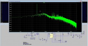
I'm also planning on looking at the output of the DAC with the rudimentary FFT capability on my Rigol oscilloscope. Might be best to go straight to that.
Regards, Dave.
The Rigol FFT will show you most of what you are interested in. The usual 50 KHz low pass filter for DDS is pretty simple and a cap could be enough for a quick verification.
Adding noise to a circuit in a .tran simulation & FFT
For getting started adding noise in LTspice see https://www.mikrocontroller.net/attachment/141892/randrandomwhite.asc
An example here "Amplifier" for adding noise to an opamp for a .tran simulation. Normal Noise analysis in SPICE is an extension of the .ac frequency domain - I think you want time domain analysis followed by FFT.
The files can be downloaded. You probably still need the bench tests as a reality check on sims.The LM7171 is 14uV/RtHz (input referred) above the corner frequency of 10kHz and below 10kHz it rises as Sqrt(freq). Below 10kHz it is pink noise and above 10kHz it is white noise. I use recorded pink noise added to the opamp input and LTspice White(t) function for white noise flat up to 1MHz
- Home
- Design & Build
- Software Tools
- Installing and using LTspice IV (now including LTXVII), From beginner to advanced