Stepping a component.
Sometimes it is really useful to be able to alter a value of a part without actually editing and re-running a simulation. This can be done by "stepping" the part in question through a set of predetermined values.
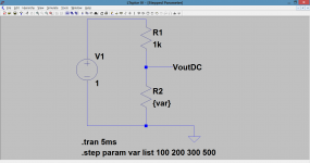
What we will do here is build on the basic command and hopefully take it in stages to something more useful. As a starting create the following circuit. Its just a DC voltage and two series resistors. The value of the lower one is the one we want to alter and so we give it a value of {var} Note the squiggly type bracket symbol that is used. Set the sim up to run as a "Transient" and use a value of 5ms (that value will make more sense later on). Now we need to choose values that we want to use for this variable and we shall pick 100, 200, 300 and 500 ohms. Next we need to enter those into the sim and we do this using the step param directive.
The full syntax is .step param var list 100 200 300 500
That will allow LT to call up each of those values in turn for ANY resistor marked {var} on our circuit diagram.

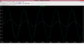
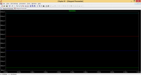
When you run the sim and probe Vout you will see three traces, each showing the DC voltage expected for each resistor.

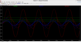
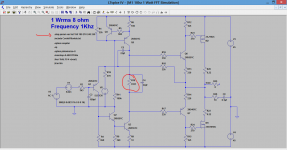
Next we will build on this and add another stepped component, in this case another resistor but this time fed from an AC source. Set the circuit up as shown with the AC source as 1 volt 1kHz. Label the output node VoutAC. Running the sim now produces two sets of traces and you can see that the peak voltage of the AC signal matches the DC values of the first sim.


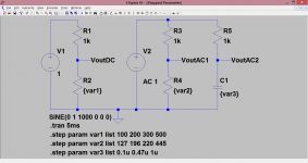
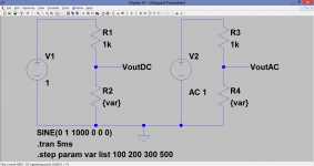
What if we want to step a couple of variables ? or three ? and make them all different. Have a look at this example. Here we have our DC source, the AC source which has had its output relabelled VoutAC1 and now we have added a resistor and cap divider also running off the same AC voltage source.

Look at the three variable components. We are now going to alter each to represent a single item in its own right so that stepping one does not interfere
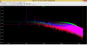
with stepping of another. All we do is call each one {var1} and {var2} and so on and create a .op line for each list. Notice the cap list is 0.1u 0.47u etc signifying 0.1uf (microfard). If we run the sim we can display all traces together (which is messy) or just an individual one (by clicking on the trace of interest at the top of the plot pane). Here is the cap trace. Notice how each shows not just the "attenuation" of each cap but also the phase difference each introduces. Pretty neat eh 🙂

And here are just the cap traces.

Sometimes it is really useful to be able to alter a value of a part without actually editing and re-running a simulation. This can be done by "stepping" the part in question through a set of predetermined values.
What we will do here is build on the basic command and hopefully take it in stages to something more useful. As a starting create the following circuit. Its just a DC voltage and two series resistors. The value of the lower one is the one we want to alter and so we give it a value of {var} Note the squiggly type bracket symbol that is used. Set the sim up to run as a "Transient" and use a value of 5ms (that value will make more sense later on). Now we need to choose values that we want to use for this variable and we shall pick 100, 200, 300 and 500 ohms. Next we need to enter those into the sim and we do this using the step param directive.
The full syntax is .step param var list 100 200 300 500
That will allow LT to call up each of those values in turn for ANY resistor marked {var} on our circuit diagram.
When you run the sim and probe Vout you will see three traces, each showing the DC voltage expected for each resistor.
Next we will build on this and add another stepped component, in this case another resistor but this time fed from an AC source. Set the circuit up as shown with the AC source as 1 volt 1kHz. Label the output node VoutAC. Running the sim now produces two sets of traces and you can see that the peak voltage of the AC signal matches the DC values of the first sim.
What if we want to step a couple of variables ? or three ? and make them all different. Have a look at this example. Here we have our DC source, the AC source which has had its output relabelled VoutAC1 and now we have added a resistor and cap divider also running off the same AC voltage source.
Look at the three variable components. We are now going to alter each to represent a single item in its own right so that stepping one does not interfere
with stepping of another. All we do is call each one {var1} and {var2} and so on and create a .op line for each list. Notice the cap list is 0.1u 0.47u etc signifying 0.1uf (microfard). If we run the sim we can display all traces together (which is messy) or just an individual one (by clicking on the trace of interest at the top of the plot pane). Here is the cap trace. Notice how each shows not just the "attenuation" of each cap but also the phase difference each introduces. Pretty neat eh 🙂
And here are just the cap traces.
Attachments

Hi,
what if you want to step the two halves of the primary in a PP transformer?
how to sintax the directive to have displayed the var, in the two components contemporarily, not one and then the other..
what if you want to step the two halves of the primary in a PP transformer?
how to sintax the directive to have displayed the var, in the two components contemporarily, not one and then the other..
Hi,
what if you want to step the two halves of the primary in a PP transformer?
how to sintax the directive to have displayed the var, in the two components contemporarily, not one and then the other..
I've not done much at all with wound components... honest answer, I don't know 🙂 There are a lot of variables on setting up a transformer sim, I would imagine (guess) you could alter and step the parameter in question as like other components... no... yes ? Its not something I have ever played around with though.
Maybe some of the others have the answer to that one.
Stepping the bias of an amplifier.
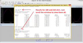
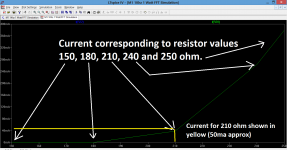
Lets now put some of this into practice on a real amp and for this I've chosen my own lateral fet design. In the first instance we will step the bias setting resistor R10 through five values between 150 and 250 ohm going up in 30 ohm steps. The Spice directive is .step param var list 150 180 210 240 270
and the resistor in question is R10. Set the sim to run as a "DC op pnt" and run.

If you now probe either of the two 0.22 ohms in the FET drains you will see this. Notice that because of the variable command the sim is now an active trace of what is going on.

You can see the five distinct points corresponding to the five resistor values chosen and for each point a corresponding bias current in the outputs.
More is better...
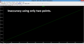
What then if we just picked an upper and lower value of resistance to try ? Well we could test it and see. Lets choose 150 and 250 ohms corresponding to our min and max values above and run the sim again.

This time we get a nice transfer characteristic but its not accurate. LT has just joined up the two dots. For example in the first run we could see that around 220 ohms might give a current of 100ma. Here though it gives nearer 250ma, and that is inaccurate. So we need more points and as such more really is better.
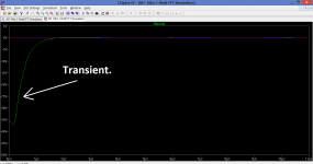
At this point it seems wise to mention a peculiarity I noticed with the sim. The keen eyed might have spotted that the 8 ohm load resistor is not connected and the reason for this is that the sim with the {var} command seems to generate a transient pulse right at the start that renders the readings meaningless (try it and measure the current in the lower 0.22 ohm). This shows the spike which is not present with a fixed single value for R10. If the load is present then this transient generates a massive current in the (lower) 0.22 ohm.
I have no explanation for the reason for this.

So continuing on... we can set the sim up and examine the effect of changes in bias current on distortion. We change from a "DC op pnt" sim to a "Transient" and reconnect the load resistor. Running the sim produces a complete entry in the spice error log that shows the distortion for each step
change in bias (refer to earlier installments on how to measure the distortion of an amplifier).

We can also look at the FFT plots and here we see a result for each change in bias. Slightly messy and meaningless.

The .asc file is attached along with the models needed. Keep them both in the same folder and the file will run straight off. The load resistor is disconnected.
Lets now put some of this into practice on a real amp and for this I've chosen my own lateral fet design. In the first instance we will step the bias setting resistor R10 through five values between 150 and 250 ohm going up in 30 ohm steps. The Spice directive is .step param var list 150 180 210 240 270
and the resistor in question is R10. Set the sim to run as a "DC op pnt" and run.
If you now probe either of the two 0.22 ohms in the FET drains you will see this. Notice that because of the variable command the sim is now an active trace of what is going on.
You can see the five distinct points corresponding to the five resistor values chosen and for each point a corresponding bias current in the outputs.
More is better...
What then if we just picked an upper and lower value of resistance to try ? Well we could test it and see. Lets choose 150 and 250 ohms corresponding to our min and max values above and run the sim again.
This time we get a nice transfer characteristic but its not accurate. LT has just joined up the two dots. For example in the first run we could see that around 220 ohms might give a current of 100ma. Here though it gives nearer 250ma, and that is inaccurate. So we need more points and as such more really is better.
At this point it seems wise to mention a peculiarity I noticed with the sim. The keen eyed might have spotted that the 8 ohm load resistor is not connected and the reason for this is that the sim with the {var} command seems to generate a transient pulse right at the start that renders the readings meaningless (try it and measure the current in the lower 0.22 ohm). This shows the spike which is not present with a fixed single value for R10. If the load is present then this transient generates a massive current in the (lower) 0.22 ohm.
I have no explanation for the reason for this.
So continuing on... we can set the sim up and examine the effect of changes in bias current on distortion. We change from a "DC op pnt" sim to a "Transient" and reconnect the load resistor. Running the sim produces a complete entry in the spice error log that shows the distortion for each step
change in bias (refer to earlier installments on how to measure the distortion of an amplifier).
We can also look at the FFT plots and here we see a result for each change in bias. Slightly messy and meaningless.
The .asc file is attached along with the models needed. Keep them both in the same folder and the file will run straight off. The load resistor is disconnected.
Attachments
or any other component you want to increase/decrease by pairs, contemporarily, by the same amount?Hi,
what if you want to step the two halves of the primary in a PP transformer?
A simple technique is to create two sets of components which are in circuit all the time, and switch one lot on and the other off, for each run. And the simplest switch, which can be repeated any number of times, is a resistor which takes 2 values of resistance in the steps - one ridiculously large, say 1TR, and the other likewise small, say 1fR - exactly equivalent to open circuit and close circuit links. Easy to do, and very useful ...
Ok, I think this is a (partial) solution:
create two distinct directives:
.step param X list .....👎
.step param Z list .....👎
replace value field in the components of interest by {X} and {Z}
run the sim
You will be given n times n results, of wich you need only the ones wich have X and Z the same figure (take a look at the Spice error log list)
Though I'm sure that there is some smarter way to do the same
Yes, the smarter way is like this:
.step param run LIST 1 2 3 4 ...
.param X=table (run, 1,X1, 2,X2, 3,X3, 4,X4, ...)
.param Z=table (run, 1,Z1, 2,Z2, 3,Z3, 4,Z4, ...)
.step param run LIST 1 2 3 4 ...
.param X=table (run, 1,X1, 2,X2, 3,X3, 4,X4, ...)
.param Z=table (run, 1,Z1, 2,Z2, 3,Z3, 4,Z4, ...)
Mooly, hi.
If you please, can you do the example (step by step) how add in LTspice models of vacuum tubes. Files with tems is attached by post #2 in the tread http://www.diyaudio.com/forums/tubes-valves/243950-vacuum-tube-spice-models.html
Thanks.
If you please, can you do the example (step by step) how add in LTspice models of vacuum tubes. Files with tems is attached by post #2 in the tread http://www.diyaudio.com/forums/tubes-valves/243950-vacuum-tube-spice-models.html
Thanks.
Mooly, hi.
If you please, can you do the example (step by step) how add in LTspice models of vacuum tubes. Files with tems is attached by post #2 in the tread http://www.diyaudio.com/forums/tubes-valves/243950-vacuum-tube-spice-models.html
Thanks.
Hi Viktor, I'll have a look into it later. I think I'll be learning too 🙂
I had a brief play earlier today and I managed to add specific models to a sim but I suspect that isn't what you want.
The file you linked to is pretty comprehensive and I'm guessing you want to be able to add any of those models at will to a sim from just that one file. (Also the few I tried from this file kept giving LT syntax errors when I tried to include them)
I'll be honest, I haven't sussed a way to do this without adding models/data to the actual LT program files, which I think is what the link jazbo8 posted is doing.
Just follow the tutorial by Stephie Bench here.
Did anyone try all this... did it work ?
The drop down menu works fine... Ayumi's models (*.INC) from the Sticky thread need to be modified in order to work in LTSpice by replacing all the "^" with "**". You also need to separate the pentode/tetrode models from the triode models, so they can be associated with the appropriate schematic symbols. Also make sure that all the pin numbers match up with the respective symbols. Do not mix the Ayumi models with the ones from other authors, because they all have different ways of assigning the pin numbers, and more importantly, the other models simply are not as accurate.😉Also the few I tried from this file kept giving LT syntax errors when I tried to include them
Did anyone try all this... did it work ?
Last edited:
Yes. I've made quite a few of them, including output xfrmrs, inverse RIAA subckts and networks etc.Did anyone try all this... did it work ?
Thanks guys, I sort of suspected as much.
So Victor, it seems there are only a couple of ways to do this...
1/ You can follow jazbo8's link and add the files to LT itself.
or
2/ You can copy the model/s of interest and paste them into a notepad file and follow essentially the same method as I used here as in post #146 which worked fine for me,
http://www.diyaudio.com/forums/soft...ng-ltspice-beginner-advanced.html#post4067126
Once you are happy with the method and a known OK model then you can work to debug and correct the syntax of the other models to run in LT as jazbo8 suggested.
Mooly, thanks.
I understand some you and jazbo'8 idea. Now a cucced in this problem a littl.
I find out how add models with spice directive .INC (.include dont work, I dont know why) . On this stage this enouth for me. I can run the simulations of my circuits. In future I will look forward to become familiar with other methods.
Onse more thanks.
I apologyze for style in wich i express my idea. English is not my nativ language.
Last edited:
Pleased it was of some help Victor and that you have at least been able to get the sims to run.
If you get stuck with anything then just ask and we'll try and help. Your English is fine 🙂
If you get stuck with anything then just ask and we'll try and help. Your English is fine 🙂
Good day everyone.
Help me please run simulation this circuit please
View attachment PP KT66.zip.
I am duplicate circuit twise in hope plot the graph of output resistanse by trying my own method. But LTspicer return error message. I dont know how repair this mistake.
PS.
Put the file "tetrode 1" in the "misc" directory.
- Home
- Design & Build
- Software Tools
- Installing and using LTspice IV (now including LTXVII), From beginner to advanced