The serial interfaces are only chained when the SERIAL CHAIN jumper is closed. If it is open, the interfaces are independent. Check the RPi pinout table in the doc to find the pin numbers.
Has anyone tested this? I haven't tried it yet, but, looking at the document: RPi GPIO pins 8 and 10 are TXD0 and RXD0, respectively. These appear to be the "standard" UART pins, typically appearing as /dev/ttyAMA0 on most RPi Linux distros.
But for the second set, the document says pins 11 and 13 for TXD1 and RXD1... does the board take care of making those pins act as another UART device? My understanding of the RPi is that by default only one serial device is available, and to use GPIO pins as a second serial device requires extra hardware.
Unless I'm missing something?
In the meantime, do you have any technique for installing the heatsink for that 5V regulator? I applied a little solder to the strips on the PCB, then painted them with flux gel. I cranked my soldering iron up almost all the way. I put the heatsink the right spot, then taped it down with kapton tape. Then I tried touching my soldering iron to those traces on the PCB. But the heatsink just absorbs all the heat, and I couldn't get anything hot enough for the solder to flow. I was afraid of keeping the iron applied too long.
To address this, what I did was put the heatsink on a cooking skillet (frying pan) at medium heat for a while. While the heatsink was heating up, I put a bunch of flux gel on the input board. Then I used tweezers to place the heatsink on the board, while at the same time using my soldering iron to heat up the solder pads on the board. There was already some solder on the pads from my previous attempt. I got some solder to melt a bit, so the heatsink is now stuck on there. Not a nice job by any means, but I suppose it's better than no heatsink. I'm afraid to keep trying for fear of ruining the board.
On the RPi there is one proper UART available, but you can use other GPIO pins as serial ports if you really have to. Search the net for bitbanging or software serial using the pigpio library. It all has to be implemented in RPi, the input board just connects the wires.Has anyone tested this? I haven't tried it yet, but, looking at the document: RPi GPIO pins 8 and 10 are TXD0 and RXD0, respectively. These appear to be the "standard" UART pins, typically appearing as /dev/ttyAMA0 on most RPi Linux distros.
But for the second set, the document says pins 11 and 13 for TXD1 and RXD1... does the board take care of making those pins act as another UART device? My understanding of the RPi is that by default only one serial device is available, and to use GPIO pins as a second serial device requires extra hardware.
Unless I'm missing something?
In general, however, the only reason to have individual serial control of two balanced DAMs once they are configured in their desired modes, is to upload firmware updates. For other things, like adjusting volume, switching inputs etc, chained serial ports work just as well and are much easier to implement.
To address this, what I did was put the heatsink on a cooking skillet (frying pan) at medium heat for a while. While the heatsink was heating up, I put a bunch of flux gel on the input board. Then I used tweezers to place the heatsink on the board, while at the same time using my soldering iron to heat up the solder pads on the board. There was already some solder on the pads from my previous attempt. I got some solder to melt a bit, so the heatsink is now stuck on there. Not a nice job by any means, but I suppose it's better than no heatsink. I'm afraid to keep trying for fear of ruining the board.
The heatsink is not needed if the input board input voltage is within the specified range, that is why it is not installed by default.
It can be a bit difficult to solder, and your approach of preheating it is probably the best way. I have used a small kitchen gas torch to preheat the heatsink and then continue heating it while applying solder wire directly to the joints. It may also work with a torch lighter.
On the RPi there is one proper UART available, but you can use other GPIO pins as serial ports if you really have to. Search the net for bitbanging or software serial using the pigpio library. It all has to be implemented in RPi, the input board just connects the wires.
In general, however, the only reason to have individual serial control of two balanced DAMs once they are configured in their desired modes, is to upload firmware updates. For other things, like adjusting volume, switching inputs etc, chained serial ports work just as well and are much easier to implement.
Thank you, that was the hint I needed. 🙂 For me, individual serial control at the hardware layer is preferred, because it's much easier to chain/un-chain as needed in software. That is, even though the general case is to send the same commands to both dam1021s, even if it's two serial devices, that chaining is trivial to do in software. And for the one time you do want independent control, you don't have to go messing with the actual hardware.
Anyway: while I do have two dam1021 boards, right now I'm just trying to get either to work with the Rpi + switch board (dual-mono will come later). Two nights ago, I had the serial connection working, but couldn't get a signal lock with music. So last night I re-read your documentation, and realized I might have to do something with the i2s select to get a signal lock, as well as ensure the dam1021 inputs are set correctly.
I'm pretty sure the dam1021 input select was set to auto, but I figured it's best to sanity check. However, last night I could not get the serial working. Nothing changed between two nights ago and last night.
I send commands like "I0", no response. I send "+++" and wait a second (which should bring up the uManager), nothing. At least two nights ago I was able to bring up the uManager.
Just to sanity check, I removed one dam1021 board and replaced it with the other. On this board, I get the same result. No matter what I do, I can't get any response from the dam1021 via serial commands.
I am certain the RPi setup is correct (basically boils down to modifying kernel params so the OS doesn't try to use the serial for its own I/O, and disabling any getty process that wants to use the UART). I double- and triple-checked that last night and this morning. (And it was working two nights ago.)
I've tried with and without the serial chain jumper in place (although I expect that for only a single dam1021, the jumper shouldn't matter).
Any thoughts on what could be wrong?
The heatsink is not needed if the input board input voltage is within the specified range, that is why it is not installed by default.
Right, but my PSU is reading a bit high (see discussion a few posts back). To be fair, I haven't measured the voltage under load. It could be my PSU is just reading high due to being unloaded. Either way, my thought was the heatsink can't hurt. If it's not needed, having it there won't cause any problems. But if it is needed, not having it could be a problem. 😉
Normunds, is it correct that the "EXT POWER" jumper must be installed when using the input board for Raspberry Pi? That is what is shown in the document in Figure 14.
I could not get serial to work between Rpi and dam1021 without installing this jumper. So it looks like the answer is "yes", just want to confirm.
Thank you!
Edit, Question #2: I cannot get an I2S lock (dam LED blinks continuously). I do not have the switch board connected. My understanding of the input board documentation suggests that I need to use the switch board to pull the I2S select pin on the Rpi in the right direction... is it possible to set I2S select correctly without installing the input board? I would like to not use the input board at all, as the Rpi will be the exclusive source for the DAC.
Thanks again!
Last edited:
Edit, Question #2: I cannot get an I2S lock (dam LED blinks continuously). I do not have the switch board connected. My understanding of the input board documentation suggests that I need to use the switch board to pull the I2S select pin on the Rpi in the right direction... is it possible to set I2S select correctly without installing the input board? I would like to not use the input board at all, as the Rpi will be the exclusive source for the DAC.
OK, I figured this out. I can set the I2S select pin from the RPi itself.
There might be other ways to do this, but I did it with the gpio utility from wiringPi. The pin numbering with this tool is somewhat confusing, though according to the author, RPi pin numbering in general is confusing. Anyway, here's the two commands I use to pull pin15/GPIO 22/wiringPi3 low:
Code:
gpio mode 3 out
gpio mode 3 down
At least, after doing this, the LED on the dam1021 goes solid when I play music. I don't actually have the outputs hooked up yet. 🙂 But the solid LED, and also "L044" over the serial indicate I'm moving in the right direction!
Edit: Wired up the outputs, we have sound! Now to see if I can get two boards working for balanced dual mono...
Last edited:
...and I have balanced dual mono working!
Two new questions:
(1) When used with the Raspberry Pi, does the Input Board use the 3.3v from the RPi? Or does it provide its own 3.3v? I would like to use one of these Allo Kali RPi I2S reclocker hats. But it does not pass the RPi's 3.3v through. Would that pose a problem for the Inboard Board?
(2) I know the Inboard board has its own on-board regulators, and therefore does not need a regulated supply. However, I can easily pass mine a regulated supply. Is there an ideal voltage to send it? I know the range is 7-9 volts. But my regulator is trimpot adjustable, might as well ease the load of the Input Board's onboard regulators.
Thanks!
Ugh, last several posts have all been by me. 😱
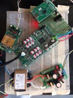
Anyway, I assume many folks out there like to look at pics, so here's a shot of my project in-progress.
This is a dual-mono setup, with Raspberry Pi and optical TOSLINK inputs.
The main setup/config is done, now I plan to focus on some fine-tuning...
Anyway, I assume many folks out there like to look at pics, so here's a shot of my project in-progress.
This is a dual-mono setup, with Raspberry Pi and optical TOSLINK inputs.
The main setup/config is done, now I plan to focus on some fine-tuning...
- Change that transformer out for one with dual 12V + dual 9V secondaries. I'll change the jumper on the DIYINHK regulator to feed the dam1021s +/- 9 VDC instead of 12 VDC. I'll use the xformer 9V secondaries to supply another regulator which will replace the Normunds PSU (so I have only one transformer in the whole system instead of two like I have now).
- Waiting to receive a rotary encoder. Will wire that to the RPi so I can have a physical knob to turn for volume.
- Case work. All the components in the picture are sitting on the bottom of the case, which is masked off for the drilling.
- Put VREF caps on bottom board. I have revision 3 boards which really don't need those caps. But I had 18 of them on hand, so only need another six to do the bottom board. It's an easy mod and makes the dam1021 boards look cool if nothing else. 🙂
Attachments
Hey, Nordmunduss, you seem to have full PM inbox. I'd like to get two pieces assembled as we spoke. 🙂
Something must of came up with Normundss. He has the parts last we spoke, they just needed to be assembled. Maybe something personal took priority over the project for the time being.
Can anyone tell me the voltage rating for the capacitors on the input board, please? This will be my first smd project, I just want to make sure that i get the correct parts and avoid as much rework as possible. Are there any other specs that I should be looking out for on any other components? I have a V2.3 board if that makes a difference.
Any help would be appreciated, thanks
-r
Any help would be appreciated, thanks
-r
Hello
I have one question: does the BPBP works like input buffer for, I.e., the hypex ucd180lp?
Those amps has no input buffer and I wonder if the BPBP will solve that.
I have one question: does the BPBP works like input buffer for, I.e., the hypex ucd180lp?
Those amps has no input buffer and I wonder if the BPBP will solve that.
Hello
I have one question: does the BPBP works like input buffer for, I.e., the hypex ucd180lp?
Those amps has no input buffer and I wonder if the BPBP will solve that.
Sorry, forget this post, It should be posted in another thread.
Hi Normundss,
It seems your inbox is full, I sent PM on 4th March 2017 but havent heard back from you. Can you please confirm if boards have been shipped? If yes then please share tracking details via PM.
Regards
It seems your inbox is full, I sent PM on 4th March 2017 but havent heard back from you. Can you please confirm if boards have been shipped? If yes then please share tracking details via PM.
Regards
Hi Normundss,
It seems your inbox is full, I sent PM on 4th March 2017 but havent heard back from you. Can you please confirm if boards have been shipped? If yes then please share tracking details via PM.
Regards
Same status/situation as me.
All the remaining boards have now been sold out.
In the foreseeable future I will not have time to produce another batch, so most likely this was the last run.
If I do get the time to work on these things later in the year, I might come up with a more generic DAC input module based on the XMOS chip that would include built-in USB input, as well as SPDIF inputs and support for remote control (input switching and volume, maybe also DAM filter switching).
- Home
- Group Buys
- Input and switch boards for Soekris DAM1021 DAC