Hi Normundss,
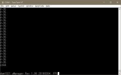
Seems some unwanted signals are populated from RPi to DAM serial. This not only causes the aforementioned volume pot noise issue, but also causes the DAM to hang (refer to attached screen capture of DAM RS232) occasionally. Your comment on this is appreciated.
Thanks!
Seems some unwanted signals are populated from RPi to DAM serial. This not only causes the aforementioned volume pot noise issue, but also causes the DAM to hang (refer to attached screen capture of DAM RS232) occasionally. Your comment on this is appreciated.
Thanks!
Attachments
Last edited:
Ahh, perhaps you have Linux console or something else configured to run on the RPi serial port.
You can either:
1) disable whatever is using the RPi serial port
2) disconnect RPi serial ports from DAM by removing the RN3 resistor array. In this case you will no longer be able to access the DAM serial port from RPi.
You can either:
1) disable whatever is using the RPi serial port
2) disconnect RPi serial ports from DAM by removing the RN3 resistor array. In this case you will no longer be able to access the DAM serial port from RPi.
Hi Normundss,
Seems some unwanted signals are populated from RPi to DAM serial. This not only causes the aforementioned volume pot noise issue, but also causes the DAM to hang (refer to attached screen capture of DAM RS232) occasionally. Your comment on this is appreciated.
Thanks!
Many thanks Normundss!
Just removed RN3 and now everything works like a charm.
Just removed RN3 and now everything works like a charm.
Ahh, perhaps you have Linux console or something else configured to run on the RPi serial port.
You can either:
1) disable whatever is using the RPi serial port
2) disconnect RPi serial ports from DAM by removing the RN3 resistor array. In this case you will no longer be able to access the DAM serial port from RPi.
Hello all
I'm trying to find a muting board. If anyone has a spare or unwanted muting board, please PM me.
Thanks
I'm trying to find a muting board. If anyone has a spare or unwanted muting board, please PM me.
Thanks
I need your help guys.
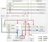
I am powering input board via power supply. It is around 8,5V DC non regulated. I also got Rpi B+ and Amanero. I am powering DAm1021 with Salas BIB +-12V.

As You can see in above picture.
I also have Reflektor D with 3,3V. I have it connected like this.

All the voltages are okey. EXP PWR is disconnected. I did measure them. The point is everything looks ok. Yet, I couldnt get it working.
Yesterday I made a little change.
I did disconnect 3,3V Reflektor, connect jumper on EXT PWR and it did worked like a charm. Then I did disconnect everything. Second time it didn`t work.
Could You see what am I doing wrong ? I can measure anything. It is just a little weird for me.
Okey.
I know how to get it works.
I have connected amanero and RPi. No more signals.
While I power up whole preamp, and Swtich board is on I2S-1 there is no sound, yet Dam1021 does lock. I can change sources, nothing helps.
To get it working, I have to switch to I2S-2 (RPi) without power. Turn it on. Then after it get up, I have to simply change to I2S-1 (Amanero). Sound is there 🙂. RPi and Amanero working.
I tested it few times. Each time same thing happens.
Why something like this happen ? Does I really have to change to I2S-2 before turning power ON ?
For the low-profile power supply that normundss designed for use with the input/switch board: is it reasonable to see around 12V on the DC output with no load? (I.e., not connected to anything except mains on the AC side and voltmeter on the DC side.)
For the low-profile power supply that normundss designed for use with the input/switch board: is it reasonable to see around 12V on the DC output with no load? (I.e., not connected to anything except mains on the AC side and voltmeter on the DC side.)
12 VDC is a little on the high side, but will not damage anything and is safe to use. If you are not powering a Raspberry Pi through it, there is no problem at all. If you are powering an RPi and the input voltage does not drop under the load, the 5V regulator on the input board is likely to get too hot after awhile.
What transformer do you use? I get around 9.2 VDC unloaded using Block FL 8/6 trafo, which has 6 VAC / 8 VA output.
Okey.
I know how to get it works.
I have connected amanero and RPi. No more signals.
While I power up whole preamp, and Swtich board is on I2S-1 there is no sound, yet Dam1021 does lock. I can change sources, nothing helps.
To get it working, I have to switch to I2S-2 (RPi) without power. Turn it on. Then after it get up, I have to simply change to I2S-1 (Amanero). Sound is there 🙂. RPi and Amanero working.
I tested it few times. Each time same thing happens.
Why something like this happen ? Does I really have to change to I2S-2 before turning power ON ?
That should not be happening.
On all switch settings except I2S-2, the I2S-1 input (Amanero) is connected to DAM I2S input. When you switch to I2S-2, the input board disconnects Amanero and connects the RPi to DAM I2S inputs. So it seems your Amanero might be causing the DAM to misbehave .
Please try it with the Amanero disconnected, see if that makes a difference.
It would be good if you can provide the power-on output from DAM serial console to see which input it actually locks when there is no sound.
12 VDC is a little on the high side, but will not damage anything and is safe to use. If you are not powering a Raspberry Pi through it, there is no problem at all. If you are powering an RPi and the input voltage does not drop under the load, the 5V regulator on the input board is likely to get too hot after awhile.
What transformer do you use? I get around 9.2 VDC unloaded using Block FL 8/6 trafo, which has 6 VAC / 8 VA output.
I am using the Triad transformer.
For 110V mains, I need to install two jumpers, right? Both J1 and J2?
Originally I only had J1 installed. I thought that might have been the source of the problem. But last night I installed J2, and I'm still seeing 12VDC on the outputs.
I do intend to power an RPi via this PSU and your input board.
6 VAC rectified ought to be 8.4 VDC after rectification. Even accounting for a 20% increase with no load is still only 10 VDC. So I suspect I have something messed up.
I'll try to review again tonight, I should be able to measure 6ish VAC on the transformer secondary, right? Any other thoughts or ideas in the meantime?
That should not be happening.
On all switch settings except I2S-2, the I2S-1 input (Amanero) is connected to DAM I2S input. When you switch to I2S-2, the input board disconnects Amanero and connects the RPi to DAM I2S inputs. So it seems your Amanero might be causing the DAM to misbehave .
Please try it with the Amanero disconnected, see if that makes a difference.
It would be good if you can provide the power-on output from DAM serial console to see which input it actually locks when there is no sound.
The same happens to me. During power if I selected I2S-2 Raspberry Pi, I can subsequently select any input without problems.
Otherwise It can block DAM1021. I think it's because Serial Data coming through the Raspberry PI serial port in the power ON.
I do not know program the Raspberry to disable the serial port. Or make this serial port to work properly with DAM1021.
Attachments


The same happens to me. During power if I selected I2S-2 Raspberry Pi, I can subsequently select any input without problems.
Otherwise It can block DAM1021. I think it's because Serial Data coming through the Raspberry PI serial port in the power ON.
I do not know program the Raspberry to disable the serial port. Or make this serial port to work properly with DAM1021.
Ahh, yes that could happen if your RPI distrubution runs console on the serial port. DAM can interpret console output as commands and mess things up.
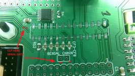
If you do not want to use the RPI serial port for controlling the DAM, you can remove the RN3 resistor array. That will be the same as cutting the tracks, except you can solder it back later 🙂
If you do want to use the RPI serial port for DAM control, you need to disable console output to the serial port.
Here are the steps I used for Raspbian:
sudo vi /boot/cmdline.txt
Remove console=ttyAMA0,115200
sudo vi /etc/inittab
Comment out getty on serial line:
#Spawn a getty on Raspberry Pi serial line
#T0:23:respawn:/sbin/getty -L ttyAMA0 115200 vt100
Reboot.
Then you can use a terminal program on the RPI, such as minicom, to connect to DAM serial port and issue manual commands. Or use the python library by DIYA member forta.
Last edited:
I am using the Triad transformer.
For 110V mains, I need to install two jumpers, right? Both J1 and J2?
Originally I only had J1 installed. I thought that might have been the source of the problem. But last night I installed J2, and I'm still seeing 12VDC on the outputs.
I do intend to power an RPi via this PSU and your input board.
6 VAC rectified ought to be 8.4 VDC after rectification. Even accounting for a 20% increase with no load is still only 10 VDC. So I suspect I have something messed up.
I'll try to review again tonight, I should be able to measure 6ish VAC on the transformer secondary, right? Any other thoughts or ideas in the meantime?
Yes, you should have two jumpers installed for 115VAC power, which will put the two primary windings in parallel. The two jumpers should be installed below the 115V marking. It corresponds to the two connected jumpers in the posted schematic. If you only had one jumper installed, the transformer was running on only one of the two primary windings, which should not cause excess output level.
For 230V input there is one jumper to the side, which will connect the primaries in series. On the schematic that would be connecting pins 2-3 of J1 and opening J2. Do not install this for 115 VAC configuration.
Can you check the AC voltage on the transformer secondary when the supply is unloaded?
I just checked my build with the Triad transformer, wired for 230V input. I get about 10.9VDC unloaded and 8.3VDC when connected to the input board with DIYINHK USB interface, no RPI. The unloaded voltage is only about 1V less than yours, so maybe you are ok.
In terms of voltage, 12V is safe for the input board, the max input is 15V. The only reason I recommend lower input voltage is due to heat dissipation in U5. After awhile it will get too hot when powering RPi.
Try to connect it to the input board and RPi and check the loaded voltage. Check the temperature of U5 with your finger. It will be quite hot, but should not be so hot that you can not touch it.
Great, thank you very much for the information.Ahh, yes that could happen if your RPI distrubution runs console on the serial port. DAM can interpret console output as commands and mess things up.
If you do not want to use the RPI serial port for controlling the DAM, you can remove the RN3 resistor array. That will be the same as cutting the tracks, except you can solder it back later 🙂
If you do want to use the RPI serial port for DAM control, you need to disable console output to the serial port.
Here are the steps I used for Raspbian:
sudo vi /boot/cmdline.txt
Remove console=ttyAMA0,115200
sudo vi /etc/inittab
Comment out getty on serial line:
#Spawn a getty on Raspberry Pi serial line
#T0:23:respawn:/sbin/getty -L ttyAMA0 115200 vt100
Reboot.
Then you can use a terminal program on the RPI, such as minicom, to connect to DAM serial port and issue manual commands. Or use the python library by DIYA member forta.

Can you check the AC voltage on the transformer secondary when the supply is unloaded?
I get 8.6 on the transformer secondary with no load. So that explains the 12 VDC (8.6 * sqrt(2) = 12).
In terms of voltage, 12V is safe for the input board, the max input is 15V. The only reason I recommend lower input voltage is due to heat dissipation in U5. After awhile it will get too hot when powering RPi.
Try to connect it to the input board and RPi and check the loaded voltage. Check the temperature of U5 with your finger. It will be quite hot, but should not be so hot that you can not touch it.
OK, still not far enough along to test that, but hopefully will be able to in a week or two.
In the meantime, do you have any technique for installing the heatsink for that 5V regulator? I applied a little solder to the strips on the PCB, then painted them with flux gel. I cranked my soldering iron up almost all the way. I put the heatsink the right spot, then taped it down with kapton tape. Then I tried touching my soldering iron to those traces on the PCB. But the heatsink just absorbs all the heat, and I couldn't get anything hot enough for the solder to flow. I was afraid of keeping the iron applied too long.
I'm assuming there's a better way...
Thanks again!
I'd like to order input board and switch board, both assembled. You PM must be full.
Please see your PM.
- Home
- Group Buys
- Input and switch boards for Soekris DAM1021 DAC