I want to use headphone amp (D1X), +line out, and balanced line out.
Now I don't have anything which requires muting (no any on/off, track/res. change noise).
What do you advise to use? Drive paralel/directly all outputs, or use the output/muting board (which i have, but with few basic components).
Now I don't have anything which requires muting (no any on/off, track/res. change noise).
What do you advise to use? Drive paralel/directly all outputs, or use the output/muting board (which i have, but with few basic components).
If you remove the relays from the muting board, it will disable the muting and you no longer need to supply 5V to it. If you don't use the buffers on the muting board, and your DAM does not make noises during power on/off, there is not much point in using the muting board.
There is a section in the input board doc on running it from an external 3.3V supply.
Btw, the TOSLINK receiver should not be powered by the same supply you use for I2S interfaces. SPDIF inputs on DAM are not isolated and should be powered from a supply connected to the non-isolated side. That is why there is a second 3.3V regulator on the input boards.
I was planning to use one O-core trafo with secondarys:
7V-0 -1A
5V-0 - 2A
and use LT3042 quad parallel psu from OPC/Owen on diyaudio. it's two rails. one would be dedicated for 5V, the other for 3.3V. and then hook these up to the Input board.
I would be powering the DIYinhk 768khz Xu216 (requires 800ma), and the toslink module (3.3v 15-20ma), hdmi i2s module (3.3V 20-25ma), and not sure how to hookup the SPDIF digital RCA on the input board if I don't plan on using onboard regulators from the input board. I assume it wll work once I connect 3.3V as instructed in your manual for the input board.
I've pulled one leg on the 7805 regulator. but if I hookup 3.3V to the input board, will the other 3.3v regulator onboard still work? You gave me a suggestion to hookup the toslink module in a previous post where I included the photo.
will it be OK to power all those devices from the one dedicated 3.3V rail on the psu? I don't really need 5V if I decide to remove the muting board. But honestly i'll probably leave it anyhow to use it.
another question popped into mind. I've got a display kit from kevin Yip, it hooks to the serial header to retrieve freq info etc, and change filters. Since i'm running dual dam1021, i'd assume I'd have to hook that serial connection up to the extra 26pin connection to the RX and TX /gnd they should be chained together with the serial chain jumper on? I've asked kevin, but he suggest maybe using 3 header cable, but then i said I believe the normunds board will essentially do the same with the serial chaining. maybe i'm missing something though?
Many posts back in this thread a guy mentioned changing the LVDS for a dual soekris dam1021 setup with this part #
85411AMLF IDT | Mouser
85411AMLF
would this be possible to use on the input board, and how? One said it was essentially "ideal" for dual soekris? if so, in theory what benefit. Also is there any other modifications i'd need to make? I don't see where this ic would go. Only one other component looks like it and believe its a mosfet
Thank you for those who are able to comment on this. I'm assuming normunds would be the one that definitely knows best.
--------------
on another subject..
U3 and U4 on the input board are both 3.3v ldo.
is U3 always working with or without the External power jumper set? it looks like it's tapping off Power A+? you'd suggested to power my toslink module from J2. and does U3 power the DA101C? or spdif transfomer "pulse or whatever" Basically, will SPDIF RCA/BNC work or be powered from the U3 LDO. Or is it from 1.2V on Power +?1.2V. I'm trying to figure what amount of 3.3V i'll need to supply the board. Hoping the toslink module and spdif rca/bnc can be powered from dam1021, and potentially a hdmi i2s ouput module (20mA) as well. would that be OK to power from same source as toslink module? pwr A+.
I'll be adding external 5V and 3.3V. I'm 90% sure U3 is always going to work...so toslink can be powered, along with SPDIF and hopefully hdmi i2s module?
Last edited:
To hookup the HDMI i2s Output module. i'm seeing
RPI pins from J19:
PIN12 - I2S_BCLK_2
PIN14 - ISO_GND
PIN35 - I2S_FSCLK_2
PIN34 - ISO_GND
PIN40 - I2S_DATA_2
PIN39 - ISO_GND
I am assuming the closest ISO_GND in sequence next to each i2s pin is the correct one to pair it with.
as far as power, can I tap off the same source the toslink will be using? HDMI module uses max of 20-25mA 3.3V
PIN 8 (PWR_+3.3V)and PIN 9 (GND)+ from J2
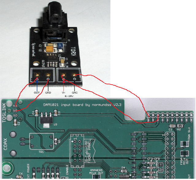
And my TOSLINK module asks for 6-20V input (MAX 40mA) albeit I swapped the component to a genuine Torx 142L (25mbps), kinda odd imho but appears to have it's own low noise regulator. but normunds mentioned in previous post to use PWR A+ and GND from J2. so my external regulated PSU (10V) that powers the dam, will also power Toslink.
RPI pins from J19:
PIN12 - I2S_BCLK_2
PIN14 - ISO_GND
PIN35 - I2S_FSCLK_2
PIN34 - ISO_GND
PIN40 - I2S_DATA_2
PIN39 - ISO_GND
I am assuming the closest ISO_GND in sequence next to each i2s pin is the correct one to pair it with.
as far as power, can I tap off the same source the toslink will be using? HDMI module uses max of 20-25mA 3.3V
PIN 8 (PWR_+3.3V)and PIN 9 (GND)+ from J2
And my TOSLINK module asks for 6-20V input (MAX 40mA) albeit I swapped the component to a genuine Torx 142L (25mbps), kinda odd imho but appears to have it's own low noise regulator. but normunds mentioned in previous post to use PWR A+ and GND from J2. so my external regulated PSU (10V) that powers the dam, will also power Toslink.
Last edited:
I made some changes to my post, yet, the 30min expired: (in red)
To hookup the HDMI i2s Output module. i'm seeing
RPI pins from J19:
PIN12 - I2S_BCLK_2
PIN14 - ISO_GND
PIN35 - I2S_FSCLK_2
PIN34 - ISO_GND
PIN40 - I2S_DATA_2
PIN39 - ISO_GND
I am assuming the closest ISO_GND in sequence next to each i2s pin is the correct one to pair it with.
Also i'm missing other pins to hookup from HDMI module...
it has
DATA / BCK / WCK / MCK / GND
so WCK and MCK i'm not sure about which ones to hookup on the input board.
as far as power to HDMI i2s Module, can I tap off the same power source the on-board toslink connections would be using? (i'm not using them since I have separate TOSLINK module/pcb hooked up to PWR_A+ yet using U1B pin 2 GND and pin 3 OUT)
SO HDMI i2s 3.3V power from - U1A- VCC pin 1, GND pin 2 (at least i'd be using the onboard regulator you installed and would be dedicated to the HDMi module. 😀
or
PIN 8 (PWR_+3.3V)and PIN 9 (GND)+ from J2 (which would be sharing power with dam, toslink and maybe this would be second choice to above, less desirable?)
(HDMI module uses max of 20-25mA 3.3V)
And my TOSLINK module asks for 6-20V input (MAX 40mA) albeit I swapped the component to a genuine Torx 142L (25mbps), kinda odd imho but appears to have it's own low noise regulator. but normunds mentioned in previous post to use PWR A+ and GND from J2. so my external regulated PSU (10V) that powers the dam, will also power Toslink.
Last edited:
To hookup the HDMI i2s Output module. i'm seeing
RPI pins from J19:
PIN12 - I2S_BCLK_2
PIN14 - ISO_GND
PIN35 - I2S_FSCLK_2
PIN34 - ISO_GND
PIN40 - I2S_DATA_2
PIN39 - ISO_GND
Also i'm missing other pins to hookup from HDMI module...
it has
DATA = DATA_2
BCK = BCLK_2
WCK = FSCLK_2
MCK = not needed?
GND = obvious. but assume this hooks up to PIN39
I'm pretty sure MCK is Mclk and doesn't matter with the dam1021.?>
When using the input board for dual mono balanced dam1021 config, my understanding is that the serial interfaces of the dac boards are chained. Is it possible to get independent serial control of the boards?
When using the input board for dual mono balanced dam1021 config, my understanding is that the serial interfaces of the dac boards are chained. Is it possible to get independent serial control of the boards?
The serial interfaces are only chained when the SERIAL CHAIN jumper is closed. If it is open, the interfaces are independent. Check the RPi pinout table in the doc to find the pin numbers.
WCK = FSCLK_2To hookup the HDMI i2s Output module. i'm seeing
RPI pins from J19:
PIN12 - I2S_BCLK_2
PIN14 - ISO_GND
PIN35 - I2S_FSCLK_2
PIN34 - ISO_GND
PIN40 - I2S_DATA_2
PIN39 - ISO_GND
I am assuming the closest ISO_GND in sequence next to each i2s pin is the correct one to pair it with.
Also i'm missing other pins to hookup from HDMI module...
it has
DATA / BCK / WCK / MCK / GND
so WCK and MCK i'm not sure about which ones to hookup on the input board.
MCK is not used.
Make sure to run a separate GND wire next to each data line.
The I2S module should be powered from an isolated supply. You can tap 3.3V from input board U4.as far as power to HDMI i2s Module, can I tap off the same power source the on-board toslink connections would be using? (i'm not using them since I have separate TOSLINK module/pcb hooked up to PWR_A+ yet using U1B pin 2 GND and pin 3 OUT)
SO HDMI i2s 3.3V power from - U1A- VCC pin 1, GND pin 2 (at least i'd be using the onboard regulator you installed and would be dedicated to the HDMi module. 😀
or
PIN 8 (PWR_+3.3V)and PIN 9 (GND)+ from J2 (which would be sharing power with dam, toslink and maybe this would be second choice to above, less desirable?)
(HDMI module uses max of 20-25mA 3.3V)[/COLOR]
And my TOSLINK module asks for 6-20V input (MAX 40mA) albeit I swapped the component to a genuine Torx 142L (25mbps), kinda odd imho but appears to have it's own low noise regulator. but normunds mentioned in previous post to use PWR A+ and GND from J2. so my external regulated PSU (10V) that powers the dam, will also power Toslink.
Do not power it from DAM +3.3V or from U3 on the input board. They are not isolated from the DAM.
TOSLINK is connected to the non-isolated side of DAM. Since your module has its own regulator, you can power it directly from DAM PWR A+. U3 regulator on the input board does the same thing - it supplies separate +3.3V rail for TOSLINK receiver.
All,
I am using the input board with pi3 and unmodified Amanero.
Pi3 power is supplied through its own USB with R3 resistor removed.
I am supplying the input board with 8V DC.
My issue is, the serial and i2s between pi and DAM only works when the Amanero is connected. I then read through a lot of posts here and found out I will need to close the external jumper and modify Amanero to use the onboard supply from the input board.
I am not keen on modifying the Amanero and don't want to use the Amanero supply to power the input board logic as it may not be available sometime. Has anyone managed to use the input board supply without modifying the Amanero board?
Is there anything else I can do to make it work in the configuration I have?
(One thing comes to my mind is to close the external power jumper and cut the track that supplies the power to Amanero. But just wanted to check if any other simpler solution is available)
All,
I am using the input board with pi3 and unmodified Amanero.
Pi3 power is supplied through its own USB with R3 resistor removed.
I am supplying the input board with 8V DC.
My issue is, the serial and i2s between pi and DAM only works when the Amanero is connected. I then read through a lot of posts here and found out I will need to close the external jumper and modify Amanero to use the onboard supply from the input board.
I am not keen on modifying the Amanero and don't want to use the Amanero supply to power the input board logic as it may not be available sometime. Has anyone managed to use the input board supply without modifying the Amanero board?
Is there anything else I can do to make it work in the configuration I have?
(One thing comes to my mind is to close the external power jumper and cut the track that supplies the power to Amanero. But just wanted to check if any other simpler solution is available)
There is no really easy way of doing what you want, but you could remove the two 3.3V pins from Amanero connector. It could also be done with the 2x10 female connector that is soldered to the input board.
Hi Normundss,
I am just starting to put DAM & input/switch boards together and will need the information of I2S default setting change details (refer to earlier communication below) so that RPi can be auto-switchable. Appreciate if you can provide it in your convenience.
http://www.diyaudio.com/forums/group-buys/269943-input-switch-boards-soekris-dam1021-dac-43.html#post4665013
Hi Normundss,
I am just starting to put DAM & input/switch boards together and will need the information of I2S default setting change details (refer to earlier communication below) so that RPi can be auto-switchable. Appreciate if you can provide it in your convenience.
http://www.diyaudio.com/forums/group-buys/269943-input-switch-boards-soekris-dam1021-dac-43.html#post4665013
Thanks for reminding me, I will add it by the end of this week.
Thanks a lot Normundss! It will be just the right time for my build.
Thanks for reminding me, I will add it by the end of this week.
Noise when using volume pot with RPi attached to Input Board
I have encountered problem when played music from Raspberry Pi (RPi), which attached to Input Board, I could only hear noise for most pot positions. Originally, this issue was posted on DAM thread below as I thought this was a DAM issue,
http://www.diyaudio.com/forums/vend...magnitude-24-bit-384-khz-575.html#post4770669
Since it's more Input Board related, I re-posted it here. As RPi streaming is my main music player, I appreciate any help/comment to resolve the noise issue when using volume pot with RPi attached to Input Board.
Thanks!
Hi Normundss,
After further tests, I found that volume pot works for all sources (toslink, coax and Amanero USB) except RPi. Could you help to investigate and advise.
Thanks!
After further tests, I found that volume pot works for all sources (toslink, coax and Amanero USB) except RPi. Could you help to investigate and advise.
Thanks!
I have encountered problem when played music from Raspberry Pi (RPi), which attached to Input Board, I could only hear noise for most pot positions. Originally, this issue was posted on DAM thread below as I thought this was a DAM issue,
http://www.diyaudio.com/forums/vend...magnitude-24-bit-384-khz-575.html#post4770669
Since it's more Input Board related, I re-posted it here. As RPi streaming is my main music player, I appreciate any help/comment to resolve the noise issue when using volume pot with RPi attached to Input Board.
Thanks!
I have uploaded an updated documentation with instructions for using RPi I2S input in DAM1021 auto mode. Use the link in the first post of this thread to download it.
That is strange.
What sample rate do you use on the RPi?
Are you sure the DAM1021 isolators and the input board are powered when using the RPi?
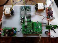
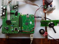
Can you post pictures of your build?
What sample rate do you use on the RPi?
Are you sure the DAM1021 isolators and the input board are powered when using the RPi?
Can you post pictures of your build?
Hi Normundss,
After further tests, I found that volume pot works for all sources (toslink, coax and Amanero USB) except RPi. Could you help to investigate and advise.
Thanks!
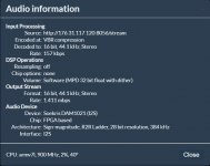
The audio source is Internet radio played with Moode Player. The audio rate is 16bit, 44.1kHz, 157kps.
DAM1021 and the input board are powered when using the RPi. The pictures of my temp build are attached for your reference.
Thanks!
DAM1021 and the input board are powered when using the RPi. The pictures of my temp build are attached for your reference.
Thanks!
That is strange.
What sample rate do you use on the RPi?
Are you sure the DAM1021 isolators and the input board are powered when using the RPi?
Can you post pictures of your build?
Attachments
Many thanks for the instructions for using RPi I2S input in DAM1021 auto mode.
I have uploaded an updated documentation with instructions for using RPi I2S input in DAM1021 auto mode. Use the link in the first post of this thread to download it.
- Home
- Group Buys
- Input and switch boards for Soekris DAM1021 DAC