Federmann, this is a beginner's amplifier, but it is designed to sound good. This is because the feedback is minimum, the GBW is maximum, and the open loop bandwidth is high.
... and no source resistors for paralleled IRF240/9240 devices. Sorry John, this is not any real world amplifier.
... and no source resistors for paralleled IRF240/9240 devices. Sorry John, this is not any real world amplifier.
No fear, amplifier performs very well, just not the time to complete. Exact building instructions not disclosed, but part of it.
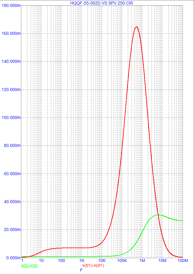
Blue - Vdif
Green - the size of the current collector transistor
Red - green derivative (to highlight errors)
Yeah I see that, but it's just a tone with it's 3rd harmonic in phase. So, no phase shift, no modulation (unless you call harmonic distortion 'gain modulation' which I can also agree to).
Sorry I came here late and am trying to find out what the issue is.
jd
... and no source resistors for paralleled IRF240/9240 devices. Sorry John, this is not any real world amplifier.
it can work without source resistance, but only with hitachi
devices, 2SJ50/2SK135 or the TOP3 variants 2SJ162/2SK1058,
provided they are very well matched, as the point of thermal
indifference is at 100 mA for these devices..
still, in my design, they are always presents...
with IRFs, it s hopeless, and even dangeourous...
I agree, but he builds it with IRF240/9240. That's why Upupa, me and others do not believe it is a real, usable thing.
We don't need instruction manual, Federmann...you don't have still functional sample...
And don't forget my first questions - which load, which voltage...
And don't forget my first questions - which load, which voltage...
Last edited:
Not dangerous, just difficult. He has thermal tracking.
No help for current distribution between such dissimilar devices as IRFs. These are not Sanken BJTs.
Yeah I see that, but it's just a tone with it's 3rd harmonic in phase. So, no phase shift, no modulation (unless you call harmonic distortion 'gain modulation' which I can also agree to).
Sorry I came here late and am trying to find out what the issue is.
jd
Image does not show the phase angle, the image does not show modulation. Picture shows Vdif and when Vdif reaches the nonlinear region. Non-linear ways of modulation.
Example 1
The frequency of 100Hz, amplitude 1V, gain 20dB, gain without feedback 80dB, output voltage 10V, Vdif 100μV,
phase 0 °
arcsin (Vdif / U(a)
arcsin = 0.00001 = 0,0005,73 °
Power 4Ω 25W, about 0.00005% THD
The frequency of 100kHz, 1V amplitude, gain 19 dB, output voltage 9V, gain without feedback 39 dB, Vdif 100mV,
Phase 5.74 °
arcsin (Vdif / U(a)
arcsin 0.1 = 5.74 °
Power 4Ω 20W, about 0.005% THD
Example 2
Acoustic signal 100Hz + 1 period 100kHz
Peak, rising edge, falling edge, always different.
Amplifier suppresses 100kHz -1dB, Vdif large 100mV, input transistors in the non-linear, the emergence of mutual modulation of signals. Distortion is non-periodic, distortion is heard, how much bias?
Distortion is generated by rapid changes. Distortion is not measured at a constant signal. The human ear hears what does not belong there.
I agree, but he builds it with IRF240/9240. That's why Upupa, me and others do not believe it is a real, usable thing.
i beg to differ...as a fireplace, it can work...
i beg to differ...as a fireplace, it can work...
Yes, as a firework.
i beg to differ...as a fireplace, it can work...
The topic is about something else when the results of measurements HQQF completed, and will set a new thread, it is premature to put out the hasty conclusions.
No such relation exists. You do not distinguish linear and non-linear distortions. Phase shift is a linear distortion, though THD is a non-linear distortion. Linear distortion does not create new harmonic components. Non-linear distortion creates new harmonic components, on multiples of basic frequency, that were not present in the original signal. Your permanent mixing of phase angle and THD is just confusing for those who are not experienced in the subject.
What rubbish, phase shift is caused by non-linearity so is second and third order products. Where did you go to school?
The topic is about something else when the results of measurements HQQF completed, and will set a new thread, it is premature to put out the hasty conclusions.
federmann, as aknowledged by your site, you look to be someone
very intelligent, but it s useless re inventing what is already a norm..
i invite you to take some inspirations from renowed designers, you
will spare yourself a lot of waste of time and money...
all the best,
wahab
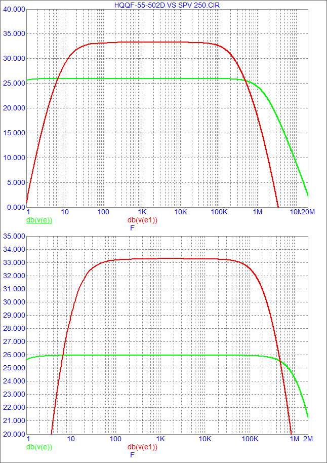
HQQF bandwidth is 4 times larger than the bandwidth QQF, but everything is still only approximate.
Image does not show the phase angle, the image does not show modulation. Picture shows Vdif and when Vdif reaches the nonlinear region. Non-linear ways of modulation.
Not sure I follow you here. Yes, there is a phase shift between input and output. That phaseshift increases with frequency. So the input signal, and the feedback signal are increasingly out of phase with increasing frequency.
Therefor, the feedback no longer exactly cancels the fraction of the output signal with the input signal, there is an increasing Vdiff (=Vin-Vfeedback) and distortion rises with frequency because feedback is increasingly ineffective. That's how feedback works.
BUT the distortion component, which is generated by the forward path, shown in your graph, is exactly in phase with the input signal. So I don't see what else there is except plain harmonic distortion. And yes, that is a form of amplitude modulation.
jd
What rubbish, phase shift is caused by non-linearity so is second and third order products. Where did you go to school?
I went to School of Hard Knox.
There are all sorts of things that cause phase shift. The most common is frequency response irregularities- in a minimum phase system, phase is the derivative of amplitude versus frequency even if the transfer function is linear with amplitude. And there's all-pass filters for those who like non-minimum phase.
What rubbish, phase shift is caused by non-linearity so is second and third order products. Where did you go to school?
There is some use of the term 'linear distortion' for freq response and phase response irregularities, versus 'non-linear distortion' for harmonic component generations.
Not everybody agrees to this distinction, but ist is usefull because it shows that the mechanisms are not always the same. Phase shifts do not cause new harmonics, but non-linearities do.
Also, even in a perfectly linear system, without any harmonics, freq response roll-off causes phase shifts.
jd
Two topology, 100kHz to see when it will Vdif in non-linear region.
Amplification without feedback
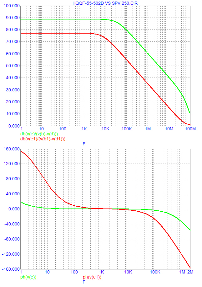
Output Phase
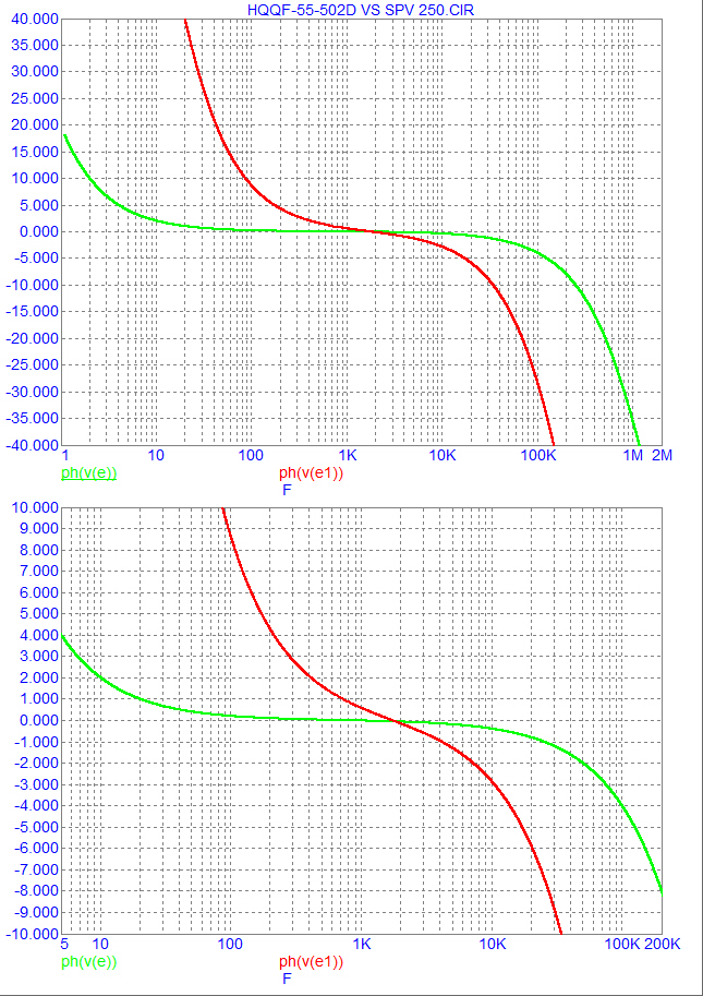
Vdif
Amplification without feedback
Output Phase
Vdif
- Status
- Not open for further replies.
- Home
- Amplifiers
- Solid State
- Influence of the delay amplifiers for listening characteristics