The unbalanced input connection is IN0A (R-ch), IN1A (L-ch), and IN0B and IN1B are connected to the GND pin to make it a common GND.
For this connection, I referred to the connection method of the unbalanced input of infineon's HP EVAL_AUDIO_MA12070 evaluation board.
User manual for MERUS ™ evaluation boards
https://www.infineon.com/dgdl/Infin...N.pdf?fileId=5546d462689a790c0168be75a3f0496c
User manual for MA120xxx reference boards
https://www.infineon.com/dgdl/Infin...N.pdf?fileId=5546d46269bda8df0169da3392a743bd
As for the input capacitor, 1uF is arranged on the board for each pin of IN0A, IN0B, IN1A, IN1B.
Last edited:
I received several types of preamps and volumes that connect to the inputs of the MA12070 board I ordered from AliExpress today. I will use these to observe changes in noise.
Can you share some photos of your setup?
What did you do with the negative input pin? Did you decouple it with a capacitor and connect it to GND?
Board does have the cap per input already.
On the PCB there appears to be no output filter coil.
Is it better to add one to cut very high frequencies?
Is it better to add one to cut very high frequencies?
The PCB has beads followed by caps for that function.
It would help to observe the board carefully and to measure it to be able to tell if it needs better filtering.
It would help to observe the board carefully and to measure it to be able to tell if it needs better filtering.
Last edited:
I have mine fired up now, running BTL 2.0. Needs trafos to create the inverted channels and they very conveniently allowed me to delete the X5R 10uF input coupling caps which are something of a constraint on the SQ.
10K:10K??????????? ???????? ?????-???
Hi everybody,
First of all, this is my first post. I have learned a lot with your comments and knowledge. I am planning to build my own amp with two boards coming from taobao of balanced version. I am planning to buy also, an interface to add options as bluetooth, usb dsd, and rca inputs, however I see that the output should be balanced so any suggestion for a module that also I can buy from taobao/aliexpress.
Sorry for my bad english, thank you very much.
The PCB has beads followed by caps for that function.
It would help to observe the board carefully and to measure it to be able to tell if it needs better filtering.
When is it 22uh coils ??
Companies like SMSL SA300 have added it, same for my MA12040 in a box on Ebay
In jargon this is called RTFM. Please read the datasheet, that one is leading compared to what manufacturer A or B may or may not do. Please also read Infineons output filter document.
https://www.infineon.com/dgdl/Infin...N.pdf?fileId=5546d46264a8de7e0164b750002861a5
Here:
https://www.infineon.com/dgdl/Infin...N.pdf?fileId=5546d46264a8de7e0164b359d78016f6
Don't create problems by thinking there are issues even before the issues really are problems. First read and make sure you are into the matter, then measure, then conclude. Only then change if necessary. Doing stuff at random by any given impulse is not the way to work.
As you can see the recommendations vary according the speaker cable length etc.
Last edited:
When is it 22uh coils ??
Companies like SMSL SA300 have added it, same for my MA12040 in a box on Ebay
Well the thing is, the loudspeaker itself has already a relatively high inductance itself.
Especially for multilevel-PWM you won't need so much filtering as reconstruction filter. So just "for the speaker" you don't really need the output-filtering as the speaker will more or less filter itself - this is also the reason why the ferrite-bead solution is working.
The only point to use a real L or LC filter at the output is if you need to meet EMI standards for e.g. CE or FCC because you are forced to test your devices in a reality-like solution in the EMC-chamber which means also you will need to test it with a couple of meters of cable.
LC filter is always a second order lowpass, a normal L is a first-order lowpass. Maybe the single-inductor solution was enough for the customer to meet those EMI requirements.
Just for you at home, you won't have any benefits of using a LC filter instead of ferrite-beads as I guess you are not planning to sell your amplifier commercially
Thanks...I just want to taste it ;-)
Any advice for a P board?
Or p based amp like smsl?
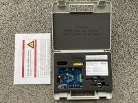
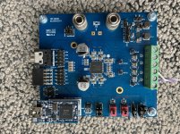
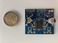
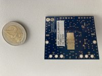
Here as promised some pics of the EvalBoards. On the big one I did already some "hand modifications"... so don't wonder.
For the small one I put a 2€ coin next to it for size comparison.
Attachments
That board with the coin - is it possible to run it via I2S or analog? From where was i bought?
//
//
Depends on the version if it is digital or analog.
You can buy it on mouser.
Digital:
REFAUDIODMA12070PTOBO1 Infineon Technologies | Mouser Deutschland
Analog:
https://www.mouser.de/ProductDetail...DIOAMA12070TOBO1/?qs=uwxL4vQweFOHvP3fLCtqUQ==
You can buy it on mouser.
Digital:
REFAUDIODMA12070PTOBO1 Infineon Technologies | Mouser Deutschland
Analog:
https://www.mouser.de/ProductDetail...DIOAMA12070TOBO1/?qs=uwxL4vQweFOHvP3fLCtqUQ==
Wow, that small board is really tempting.
Seems to be usable as 4-channel-amp or with converter as bridged 2-channel-amp. So small and well priced.
Really happy I have enough amps already! ;-)
Seems to be usable as 4-channel-amp or with converter as bridged 2-channel-amp. So small and well priced.
Really happy I have enough amps already! ;-)
@maggusxy Thanks for the detailed answer about output filtering and EMI
@Jean Paul I have also read Infineon's document on the use of EMI filtering, document PDF "EMC output filter recommendations for MA120XX (P)"
Denis
@Jean Paul I have also read Infineon's document on the use of EMI filtering, document PDF "EMC output filter recommendations for MA120XX (P)"
Denis
Last edited:
Thanks!
Wanted an amp for my subs. In the end I just now ordered one of those A07 TI based amp from France incl. a cheap toslink in DAC as I want opto connected amp.
These are still interesting I think even if matching a toslink->i2s card that works might be a challenge...
//
Wanted an amp for my subs. In the end I just now ordered one of those A07 TI based amp from France incl. a cheap toslink in DAC as I want opto connected amp.
These are still interesting I think even if matching a toslink->i2s card that works might be a challenge...
//
best board packing ever seen ;-)
Here as promised some pics of the EvalBoards. On the big one I did already some "hand modifications"... so don't wonder.
For the small one I put a 2€ coin next to it for size comparison.
That was 2 years ago before Merus was acquired by Infineon.
This is MA12070P, with the I2S interface. Later I did another revision of PCB with Schottky diodes added to protect the IC from overstressing (you can see results on the photo attached).
The sound was good thou, I still have a couple of PCBs and IC's to play with. However, I did not compare it with my TAS5548+TAS5162 amp.
Finally spent few days on these winter holidays on the second version of my Merus amplifier.

It basically consists of 3 parts: power regulation + LM25122 boost converter for PVDD, Merus chip and MCU/control logic.
This time I used another my project, the interface board, just to make bring up and debug process easier 🙂 But there is a place for Atmega8, which now does the job of merus chip initialization and encoder handling for the volume control. Signal source is the amanero-like interface board, it will work with original module without any problems, or there is also an option for on board ESP32 module:

There are 3.3uH inductors in the output filters which are not necessary. And I don't know why, but when amplifier is enabled these are quite noisy! Maybe it's just bad choise of inductors. I've never heard any noise from inductors in TI based amplifiers.
Someone mentioned here that it will be interesting to dynamically control PVDD, so since I had almost everything in place, with addition of small I2C dac I did it:

It's basically current injection in the feedback loop of the boost converter, which allows to set output voltage in 12-36V range. Can't say that I notice any difference in output power by just listening music. It does make sence because it is a closed loop amplifier. This trick works great with TI open loop amplifiers 🙂
- Home
- Amplifiers
- Class D
- Infineon MA12070 Class D