Let`s have a look at making our own PCB since it isn`t available. The parts are and I would like to make some improvements.
Good idea.
You have the schematics at the first link of post #36.
Also take a look at this.
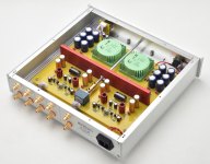
Isn't it pretty ?
Patrick
.
You have the schematics at the first link of post #36.
Also take a look at this.
Isn't it pretty ?
Patrick
.
Attachments
Last edited:
Let`s have a look at making our own PCB since it isn`t available. The parts are and I would like to make some improvements.
😀😀
Let`s have a look at making our own PCB since it isn`t available. The parts are and I would like to make some improvements.
Chris & i are already working on a proper schematic drawing. My second all SS circuit drawing, i am figuring some stuf fout (like how to represent the LSK). I can fumble my way round a tube circuit but i have yet to get asolid handle on SS.
Once we have it buttone dup i’ll post it so others can start thinking about it.
dave

.....I have not received a reply. Either I’m just gonna get a refund sent to me without me asking, receive the new layout or receive the original board. Your guess is as good as mine
😕
Well, I got my answer...
Refund issued 😀
Not disappointed anymore given the latest developments here, things have a way of working out in the long run 🙂
Might want to capture your concepts into ltspice and simulate, lots of fun to learn and design
Last edited:
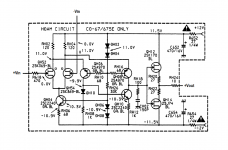
Here is the original (wired as unity gain), not the clone, which is a compromise.
https://www.diyaudio.com/forums/att...iscrete-opamp-dip8-footprint-marantz-hdam-png
Patrick
https://www.diyaudio.com/forums/att...iscrete-opamp-dip8-footprint-marantz-hdam-png
Patrick
I cleaned up for you.
You can treat this as an opamp (which the HDAM essentially is).
I'll let you change the output stage to BJT if you must.
You can also read section (F) of :
https://www.diyaudio.com/forums/att...-footprint-discrete-opamp-topologies-2019-pdf
Have fun with Spice. 🙂
Patrick
.
You can treat this as an opamp (which the HDAM essentially is).
I'll let you change the output stage to BJT if you must.
You can also read section (F) of :
https://www.diyaudio.com/forums/att...-footprint-discrete-opamp-topologies-2019-pdf
Have fun with Spice. 🙂
Patrick
.
Attachments
Hi Patrick,
Thank you very much. You have good hunting skills.
The fact does remain, the kit has excellent performance in a measured sense, and it sounds better than many very expensive preamps. I'm sure the original circuit does as well.
Hi Rick,
I'm afraid I don't know how to use any spice program. I generally build something after designing the board, then adjust values to obtain the desired performance. Then it is real and not a predicted outcome. Luckily for me, when I design something it generally works on that layout even if I have to adjust component values.
Hi Patrick,
No, it is ancient as far as designs go. I always wondered why it didn't get the attention and development it deserves.
-Chris
No, it is ancient as far as designs go. I always wondered why it didn't get the attention and development it deserves.
-Chris
Well, in the end, it is still a single-ended opamp. 🙂
In multiple rounds of private shoot-out's between the 3 topologies described in
https://www.diyaudio.com/forums/att...-footprint-discrete-opamp-topologies-2019-pdf
it was the JC-Pro that came out on top, not the HDAM (AD797-J).
Surprised me as well.
Patrick
In multiple rounds of private shoot-out's between the 3 topologies described in
https://www.diyaudio.com/forums/att...-footprint-discrete-opamp-topologies-2019-pdf
it was the JC-Pro that came out on top, not the HDAM (AD797-J).
Surprised me as well.
Patrick
Thanks Patrick.
You know what is funny? I picked up a C02 and M02 system for my bedroom. I always liked them and used to do warranty service on them.
-Chris
You know what is funny? I picked up a C02 and M02 system for my bedroom. I always liked them and used to do warranty service on them.
-Chris
If you would forgive me for hijacking.
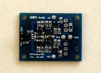
This was originally meant to be a portable headphone amp with Sziklai output.
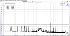
It does 0.0015% H2, and 0.0035% H3 at 0.57Vrms into 32R at gain = 10 with only 25mA bias, which is ridiculously good.
For another project, I took out the Sziklai and just used the output emitter follower as a line amp.
JFET input, all active devices available readily at Mouser / DK, very low current consumption (<10mA).
No loop negative feedback. DC stable to +/-1mV without servo.
Just to show you what can be achieved without resorting to unobtaniums.
Cheers,
Patrick
This was originally meant to be a portable headphone amp with Sziklai output.
It does 0.0015% H2, and 0.0035% H3 at 0.57Vrms into 32R at gain = 10 with only 25mA bias, which is ridiculously good.
For another project, I took out the Sziklai and just used the output emitter follower as a line amp.
JFET input, all active devices available readily at Mouser / DK, very low current consumption (<10mA).
No loop negative feedback. DC stable to +/-1mV without servo.
Just to show you what can be achieved without resorting to unobtaniums.
Cheers,
Patrick
Attachments
Hi Patrick,
No problem. We are talking about an alternative to that kit. All the parts are available and also easily substituted.
I would suggest that using increased bias current to optimize the distortion performance would be reasonable, removing low current draw from the design requirements.
How does everyone feel about a surface mount version? All the current devices that are good seem to be in this format.
-Chris
- Home
- Source & Line
- Analog Line Level
- Inexpensive preamp kit on Ebay