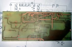
The last image from Eddie, related to during construction of GEM
One more may be posted near future, showing his finished amplifier as well as his comments about the unit sonic quality.
This Brazilian Forum have only young guys, and they are more focused into automobile amplifiers....car sound.
Yes...will be very good to see the schematic made by Eddie, because of part numbers maybe. Soon i will have it to post.
Those three are exception.
regards,
Carlos
Attachments

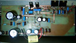
Carlos !  These Toshibas are never originals !
Look at this thread to see how originals look like:
http://www.diyaudio.com/forums/showthread.php?s=&threadid=82638
Mike 🙁
These Toshibas are never originals !Look at this thread to see how originals look like:
http://www.diyaudio.com/forums/showthread.php?s=&threadid=82638
Mike 🙁
Yes, i told him about....but he will try those ones.
Let's see, very soon, what he perceived with those transistors shown.
regards,
Carlos
Let's see, very soon, what he perceived with those transistors shown.
regards,
Carlos
This worries me deeply...produces inside me deep concerns
As those things...bang listeners, can "burn" amplifier's public images.
I do not know how is Eddie's competence as a listener....as audiophile, i was never near him to check his skills....oh!...this makes enormous differences.
I have a friend that cannot perceive when the amplifier is entering the clipping.... he just cannot perceive...this is a problem.
I will talk with him again...and will tell him that written evaluations will be accepted only if he replace those units, at least, for evaluation purposes.
To talk 100 percent true....i cannot even know my competence as a listener...there's no instrument available as "Audiophile rate"...that's a new problem...i could evaluate Eddie, you can evaluate me, another will evaluate you...and ho will evaluate the first one of the sequence?.....hehe...problem
thank you Michael.
regards,
Carlos
hi.... im Eddie....
well my name is Edgar but can call me Eddie... i prefer....
as i can ill post... more picts... n comments...
i just finished... my ML_TQWT...
the pads....
1,2 - audio input
3,4,5,6 - power supply w/ 40mF
7,8 - cap 1uF Auricap bypass
9,10 - choke
dun know.... if this Toshibas r fakes.... but ill test... n report u...
well my name is Edgar but can call me Eddie... i prefer....
as i can ill post... more picts... n comments...
i just finished... my ML_TQWT...
An externally hosted image should be here but it was not working when we last tested it.
the pads....
1,2 - audio input
3,4,5,6 - power supply w/ 40mF
7,8 - cap 1uF Auricap bypass
9,10 - choke
dun know.... if this Toshibas r fakes.... but ill test... n report u...
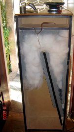
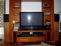
Here is an image of the "tower speaker made by Eddie"
This speaker is beeing finished to be matched with GEM.
He will adjust to other amplifiers, and them will evaluate GEM.
Finally, i suppose he will adjust those towers to match GEM .
regards,
Carlos
This speaker is beeing finished to be matched with GEM.
He will adjust to other amplifiers, and them will evaluate GEM.
Finally, i suppose he will adjust those towers to match GEM .
regards,
Carlos
Attachments
im using in this tower....
tw Hiquphon OW1.... w a solen cap of 4.7uF
and a mid made by a Paulo Ramos...
Akron KB6 with a inductor of 0.3mH 13AWG
Loudspeaker Measurement System - Linear X Systems Inc.
Method - Double Curve-Delta Mass
Domain - Free Air
Model - TSL
Size = 6"
Impedância = 8 Ohms
Potência = 60 WRMS
Resposta = 36Hz a 5K
Revc = 6.700 Ohm
Fs = 36 Hz
Sd = 13.100 m M2
Krm = 1.812 Ohm
Erm = 0.837
Kxm = 39.863 mH
Exm = 0.550
Vas = 25.323 m M3
Cms = 1.039m M/N
Mmd = 15,517 mKg
Mms = 16,379 g
BL = 8.141 T-M
Qms = 3,165
Qes = 0.356
Qts = 0.320
No = 0.400%
SPLo = 87.980 dB
xMax (One Way) = 7,5mm
xLim = 19,0mm
Le = 0.343 mH
u can see more atAKRON KB6
having some troubles... to make the choke of 2.5H.... and sure... to fit all the project into a cabinet...
cause....
its 2 toroidals, 2 capacitive banks w 40mF, a motorized pot to volume and a IR circuit to control the pot....
An externally hosted image should be here but it was not working when we last tested it.
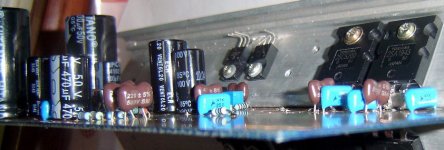
the caps.... w value 22pF 220pF, 47pF 100pF... are silvered mica...
the 100nF n 220nF 680nF... r metalized polyester
all resistors r metal film....
resistors 0.47R n 2.2R n 1R r metal oxide film....
eaoyama said:An externally hosted image should be here but it was not working when we last tested it.
the caps.... w value 22pF 220pF, 47pF 100pF... are silvered mica...
the 100nF n 220nF 680nF... r metalized polyester
all resistors r metal film....
resistors 0.47R n 2.2R n 1R r metal oxide film....
Eddi ! Your schematic contains errors, one is the missing connection between collector and base for t10. Also emitters of q1/2 are not connected.
If you built that schematic, the amp will not work at all.
sorry,
Mike
Graham visited the thread because i invited him to do..he observed that zobel
filter is missed......2,2 ohms in series with 100N capacitor ...one side into the output line and the other side connected to ground.
He told that those Toshibas...fake or not fake, will work fine in his circuit.
regards,
Carlos
filter is missed......2,2 ohms in series with 100N capacitor ...one side into the output line and the other side connected to ground.
He told that those Toshibas...fake or not fake, will work fine in his circuit.
regards,
Carlos
Hello Guys,
As I had read you previous post on this thread, I gained interest to build this amplifeir designed by Graham, but before I proceed to build one, can help me to ave a clear idea about the bias setting for this amp? You had mention that this is a class A//A/B amp, should it means that it could be biased as either as Class A or ClassA/B?
Can you give me the bias adjusment pocedure for this amp? In particular, where am I going to measure this current specified in the schecmatics.
It could help me a lot to have knowledge and experience in building this amp.
Best Regards,
Bernhix
The GEM amplifier is a standard class AB amplifier, with some different parts...and..
Has an auxiliary single ended output, constituted by a NPN transistors operating in the negative rail.
First disconnect the extra NPN transistors, the class A unit, that is connected down, in the negative rail.
Now insert 2,2 ohms resistors in series with the supplies...one resistor in series with the positive supply line and the other in series with the negative supply line.
Those are protective resistors, that will limit the current, even if the amplifier circuit presents a short circuit..... in this case, the 36 volts supply version will have a 2,2 ohms resistor drain.... where the maximum current will be something around 13 amperes...and this will depend of the suppply power...if the supply will be able to do that...Also, all voltage will be developed over this resistor, and this will protect the circuit board...as power is voltage multiplied by current...and having low voltage over the board you will have low power there...avoiding to melt or destroy something.
Those protective resistors will be helpfull as current will cross them and will produce a voltage over those resistor extremes....this voltage can be measured and using ohms law you will be able to calculate the current without the use of two series Amperimeter..... so, 220 milivots measured over those resistors will show you that 100 miliamperes are crossing the resistor beeing measured...and this is the AB current, adequated to the AB output stage.......but you can choice another current, listening and adjusting....my amplifier works with higher current in the AB stage.
When you finished to adjust the bias to the AB amplifier, connect the extra transistor colector, and measure the negative rail resistor...this one will have 100 miliamps crossing it, because of the negative rail bias to the AB output, and will show bigger current that will bias the extra transistor....let's imagine 500 miliamps to the extra NPN and 100 miliamps to the AB negative rail output....this will result in 600 miliamps, that will appear over the negative rail protective resistor as 1.32 Volts.
Of course you can use other resistor values..... 2,2 is the value i have...you can use 4.7 ohms, and it is more adequated, as will limit the current to a lower value.... you will need only to divide the voltage measured over the resistor by its own value to obtain the current that will be crossing it.
Doing that, measure the output voltage, over a 8 or 4 ohms load resistor...the voltage there must be low....something around 30 milivolts is adequated...intall a protective fuse in series with the output...3 amperes to 8 ohms loads and 6 amperes to 4 ohms loads when using 36 volts supplies.
Check if the zobel filter capacitor or resistor is showing heat (oscilations) and if everything fine...enjoy the nice sound of a GEM amplifier...also make a picture of your smiling face listening it...we gonna enjoy this too.
Remove the protective resistors before listening, as they will reduce supply voltage and will produce enormous distortions.
Yes.... stand by current and dinamic working current will be different when measuring positive rail current and negative rail current..... the negative rail will present more current drain...reason why this amplifier will not work fine connected to a bad supply..... low capacity of current will produce a big loss o voltage in the negative rail...this will produce distortions...well, there are people that apreciate this result and it is considered by many, more an effect than a defect (this is subjective).
The last GEM model, the one use a Choque at the positive rail, draining the same current in both rails in the stand by mode (not during dinamic operation when things still the same)...the last GEM works better because the EMF generated by the speaker during normal operation is partially blocked...but this inductor is an enormous "whale" inside your amplifier....an enormous coil, presenting some tenths of ohms of resistance....the Last GEM produce 100 watts over 8 ohms and uses more transistors because of that.
If you feel the need to talk with Graham Maynard, the designer, the one will explain better than i can, send me a direct mail, and i will put you in direct contact with him.
nanabrother@yahoo.com
regards,
Carlos
- Status
- Not open for further replies.
- Home
- Amplifiers
- Solid State
- Incredible quality amplifier by Graham, prepare your ears for it