Hi Carlos,
Maybe you can help me. I'm finally getting round to ordering components so that I can build myself some GEM monoblocks.
Would you or anyone else following this thread be able to advise me on what type/grade or resistors and capacitors are approriate for the GEM?
Many thanks in advance,
Grant.
Maybe you can help me. I'm finally getting round to ordering components so that I can build myself some GEM monoblocks.
Would you or anyone else following this thread be able to advise me on what type/grade or resistors and capacitors are approriate for the GEM?
Many thanks in advance,
Grant.
Resistors are Metal film units...input are ceramic, the 220 pf units
10N at the feedback line..near the feedback transistor, from base to colector can be everyone.
Small values.... for instance, refering the model 200 schematic, the 22pf in the feedback line, this one i suggest it as ceramic or Silver Mica
47 picofarads is used in series with a resistor, from base to colector in the Voltage amplifier transistor...use Silver Mica there...if you had problems...try ceramic.
You have 220nf in the differential CCS...use the one you have to that position.
Put 100N, poliester or other material you prefer, in parallel with all electrolitics condensers.
10MF as you can see in Graham schematic means 10.000 microfarads.
If you decide to make it more safe during adjustment, install another 47 ohms resistor in parallell with the 47 ohms adjustable potenciometer.... this is to reduce the voltage adjustment to bias the output Class A active transistor, the one is in the negative rail.
I hope i could help.
regards,
Carlos
Attachments
Really guys, i am in peace with Mr. Graham, but if he dislike
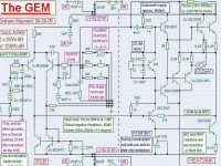
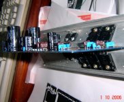
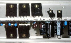
This reduced power version, that i made many monthes ago, will produce a good result for us.
As he may return to defend his design against modifications.
Well, not really modified, this is the same amplifier with reduced supply voltage, in this case using only 37 volts simetrical.... and this voltage many of us already have inside our home...because there are other amplifiers that use this voltage....so, you have only to travell wires from your other amplifier supply to feed this one..... well, if you want, you really do not need to have one supply to each amplifier...you can have separated supply to feed many units...one or two each time...or one channel of some amplfiier and other channel of the comparison amplifier...and both from the same supply..unless you are very rich.
As power will be reduced, the multiple parallelled resistor will not be needed to 8 or 4 ohms loads.
Design is the Graham Maynard with supressed transistors only.
It works fine...i have used it for monthes, now dismounted as i am needing a bigger supply and more output transistors to check the full voltage version.
I made once a full voltage version....but those days i had oscilation problems and had to include Miller capacitor....Graham did not agreed...and as i had not patience enougth to re travell my wiring once again, i let it the way it was till i had the need of some big transistor it was using.
I cannot, really, to stay with many amplifiers, even the better ones, as i need my parts to check other designs...and using the same parts...the best design appear clealy, as parts would not cooperate to better sonics...it is more probable that same parts sounding different in other designs are because of design, and not because of parts.
But really, this is the one i will reconstruct soon...and it will be made to stay in my reference unit list, ready to testings.
regards,
Carlos
Attachments
Thanks Carlos, helpful as ever, you've set me on the right track with this project.
Best wishes,
Grant.
Best wishes,
Grant.
You are welcome Ghamond....just call me and i will do all i can
To help my forum friends, the same way i was helped many times in this life.
I am already trying to pay a lot of good things that life gave me, including many friends, and all them very special.
I am very proud of them.....i use to feel myself so proud that i felt myself inflating with pride.... filled with pride as a ballon.
regards,
Carlos
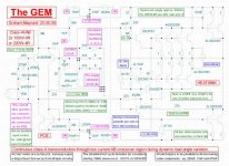
Graham produced one more upgraded circuit.
This one, in his words, is one step close to the perfection, and could win the most famous hibrid amplifier he has.
He included a choke coil....2,5 milihenries....this is really big, and he is using 230 to 50 volts transformers to perform this work.
Here the schematic.... a little crowded because too many informs, but really detailed.
regards,
Carlos
Attachments
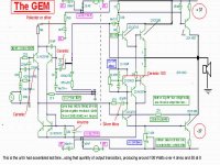
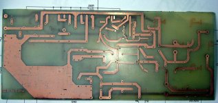
I made some split schematic copy, as Graham use a PCB only to input circuitry
At left you will see differential, CCs and auxiliary circuits.
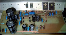
At rigth you can see the output circuit, the voltage amplifier and the VBE multiplier...both class AB outputs and class A output.
That half rigth part is to be assembled over the heatsink...or under the heatsink if you prefer, and the connections are made with medium gauge wiring, something alike telephone wires...it is a point to point connections, aerial, and over the transistors, making connections not long, never crossing, having distance one related the other not to have coupling and insulated in the positions really needed.
The left part goes over a pcboard, and observe that you have 10000uf condensers that may be better if applied near the power circuits, those are supply filter, or rail filter if you prefer to say this way.
Yes, this copied image has not the connection from output line into the feedback line...observe that no coil is used.
The amplifier produces 100W, with minimum distortion, over 4 ohms.
I did not listen this one, but i will do it soon...very soon.
Yes, it is possible that you may find something missing in the black and white schematic copy..be sure that was my mistake, the intention is just show that things are splitted, that you have a pcboard and also another complex construction, spider shape construction, depending of your habilities.
regards,
Carlos
At left you will see differential, CCs and auxiliary circuits.
At rigth you can see the output circuit, the voltage amplifier and the VBE multiplier...both class AB outputs and class A output.
That half rigth part is to be assembled over the heatsink...or under the heatsink if you prefer, and the connections are made with medium gauge wiring, something alike telephone wires...it is a point to point connections, aerial, and over the transistors, making connections not long, never crossing, having distance one related the other not to have coupling and insulated in the positions really needed.
The left part goes over a pcboard, and observe that you have 10000uf condensers that may be better if applied near the power circuits, those are supply filter, or rail filter if you prefer to say this way.
Yes, this copied image has not the connection from output line into the feedback line...observe that no coil is used.
The amplifier produces 100W, with minimum distortion, over 4 ohms.
I did not listen this one, but i will do it soon...very soon.
Yes, it is possible that you may find something missing in the black and white schematic copy..be sure that was my mistake, the intention is just show that things are splitted, that you have a pcboard and also another complex construction, spider shape construction, depending of your habilities.
regards,
Carlos
Attachments
For those who are interested in Grahams Gem amplifier, he has written a page full of information and showing the latest schematics.
http://www.zen22142.zen.co.uk/Circuits/Audio/gem100.htm
Mike
http://www.zen22142.zen.co.uk/Circuits/Audio/gem100.htm
Mike
Thank you Michael, i have lost this link, reason why i did not post
Was very nice your cooperation.
This amplifier is something very special, i am sure you would be happy with it.
regards,
Carlos
Was very nice your cooperation.
This amplifier is something very special, i am sure you would be happy with it.
regards,
Carlos

- Status
- Not open for further replies.
- Home
- Amplifiers
- Solid State
- Incredible quality amplifier by Graham, prepare your ears for it