Graham is no1 as carlos has said over and over we cant affort to lose members, we need more
cheers
cheers
Those who built it, loved it
He who designed it, took his marbles and went home
Without his support, the thread has died
Graham may still help individuals by email or have a webpage elsewhere for this project
He who designed it, took his marbles and went home
Without his support, the thread has died
Graham may still help individuals by email or have a webpage elsewhere for this project
Hello I am looking for the circuit page for the 200w gem. Could anyone point me in the right direction?
Thanks Steve
Thanks Steve
I am sorry, i could not find the home page
It may be somewhere inside my PC.
But i have his new schematic, and a lot of informs are written there
He continues with research...but has any intention to return to our forum.... what a pitty!.
Problem is that people can be unkind....can bother all time long.... cannot only broke rules...and rules do not say that we cannot bother...this is the problem.
People goes disturbing..you say Yes and them the guy say NO..you say red, people say green...always bothering...you will holding your patience...but things have some limit.
Graham Limit exploded...he thinks, the same way i think, that forum cooperators , the ones work for forum, the ones that help forum with money or any kind of help, deserves some support.
But Democracy say that everyone of us is the same in the front of the law..... in the reality this is not true....happens only between people that are not famous, not rich and not influent.
hehe
regards,
Carlos
Attachments
In the reality folks...i want Graham back
I think it is selfish to me to have his attention only to me.
He wants me to construct, in the reality he want people constructing and having fun with his amplifiers.
And they are good as a hell...they are incredible good, they are really, really, really, really very good.
But also has problems that i have asked Graham to fix...if you advance bias trimpots you will burn output unit, as you can drain all the possible current that your supply can send to your boards, at least you will have to buy many fuses.
I have asked Graham limiting resistors in series with the adjustment trimpots to avoid us to go into danger ranges of current during the class A setting of current
This Graham circuit is two in one...it has two amplifiers driven by the same input differential, one is a class A amplifier, single ended, the lower transistor will produce audio amplification, giving us guaranteed top quality single ended class A audio to low power reproduction.... around 2.5 watts, and you do not imagine how long we listen in this power range...i think some of you do not imagine that 2.5 watts each channel is much more than enougth, and average music power, without peaks, use to be adjusted inside this power range.
The GEM amplifier works in class A all time long.... wasting, lets say this way, 50 watts of energy that is transformed in heat, to produce those 2.5 watts....... but here you can find the real advantage...as it will be driving current all time long, if you have, as usually we have, some small crossover distortions in the second amplifier, the standard 100 watts unit superimposed in the schematic...included in the schematic as another power output,..well..the current beeing driven will not allow those unlinear pulses of crossover to appear...mufling them, let`s say this way.
The class B amplifier is something very standard, efficient and i do not know why produces so big dinamics...it is a bootstrapped traditional version with enormous electrolitic condenser to avoid the use of zener to stabilization, to make them simple to diy, and to avoid noises that usually are generated by the zener...well..he prefered this way...but include a interesting circuit into the input that seems to me a ccs, ...also some resistors are use to cancel phase errors, or to correct them.
Graham send me many technical details and description, but i cannot talk too much, as some friend will arrive here to make a question and it is possible that i cannot be able to answer...them i will run to Graham, and them i will run here once again...and this is not something interesting...it is not practical, not well organized and not fair with you all and not fair with me too.
I am proposing Mr. Graham Maynard to land in our forum once again, and face the problems that we have here from time to time...giving a chance to moderator to fix, to control, to act if they were needed and asked to do it.
If problems faced turn bad again to survive.... he can get out once again.... and i am afraid for ever and ever.
I do not even believe i can convince him to land here...with his enormous airplane of geniality, bring wonderfull things, result of 40 years of researches.
Having conditions to answer everyone, directly, and explaining when the amplifier can oscilate...why it can oscilate, how to avoid this, the construction technique needed, the new anti oscilation circuit.... the care needed in the adjustment and all details.
I am sure that the ones that have good amplifiers in their homes will be happy with this amplifier, it is a GEM, it is not comercial, it is a diy amplifier, free for everyone, and with qualities that may turn you astonished.
I will not face the thread alone...without Graham stand up aside me....i have not enougth knowledge to face this, and this is a very selfish priviledged informations that i have, when all forum can have this GEM.
The upper class A power transistor is holding the entire positive supply voltage and draining current for this positive side...it is able to hold the 50 positive volts to stablish the needed zero at the output line......the upper transistor is not an active device, it represents a resistance only to hold 500 miliamperes of current and 50 volts over it...so you can calculate using ohms law, the equivalent resistor needed there, if you think in this substitution..not a good idea, quality will not be the same, but construction prices will go lower.
Taking a good observations of the 200 watts amplifier you will perceive that it forces some low impedance input that can be arranged differently, also you have a resistor to help to match high impedance inputs....this is very helpfull, a very simple trick.
You may observe that it is very simple, having not too much strange circuits..only enormous electrolitic condenser that can be reduced...and will produce worst results, but still sounding nice.
The problem is that the schematic brings too much detailed informs into frames with letters inside...this turns the amplifier vision very complicated, when it is very standard and very simple...try to separate and recalculate them with resistors and equivalents circuits and you will see how simple it is.
those informations posted there, together the schematic turns it strange and crowdy, when in reality, after those informs removal, it is not complicated..... easy to calculate this amplifier, easy to modify and adapt.... very simple and easy....those more simple ideas use to produce a very nice sound (for the ones apreciate JLH designs i me).
Yes, i know that Samuel and other guy already made criticisms, made comparisons and did not give to GEM the value i believe it has...i do not agree with that evaluation, but i have to respect Samuel, as he made the amplifier and produce a comparison, and this is a very respectable way to support his thougths.
But many reasons can result bad.... parts, boards, construction, comparison technique, environment, speakers and the constructor personal WILL...as when we pay big money for something, we do not feel happy when a free and cheap diy circuit had the capacity to eat our expensive unit in the breakfast.
ahahahahah!..i am sure this amplifier is a big mouth with enormous troat, able to eat several comercial amplifiers...easy, laughing and asking for more!
Mr. Graham Maynard, please, return to our forum, this is your home too, now we have experienced moderators, and much more experienced moderators, they have banned many bad guys from here, we have Weldon, this one is alike a tiger, soflty and fast he jumped over bad guys......we have my friend from Canada...this one will not let people loose respect from you....Pinkmouse has enormous attention with details, a very fast man in the trigger, Stuart Yanniger is my friend, also Planet 10...i will ask them protection if you face problems, also i will stand aside you during the fire.
regards,
Carlos
Here is a link to Graham schematic
http://www.zen22142.zen.co.uk/Circuits/Audio/gem100.htm
I am discussing with him about his amplifier and asking his return.
regards,
Carlos
http://www.zen22142.zen.co.uk/Circuits/Audio/gem100.htm
I am discussing with him about his amplifier and asking his return.
regards,
Carlos
I also am sorry that Graham does not grace us with his presents
Thank you Carlos for responding to my inguiry. I have built the JLH 10 watt amp which I love and aquired trannis and heat sinks for the leach 6 transistor amp.
I prefer the JLH and was hoping that the Leach transformers would work on the 200w GEM 😀
Thanks again
steve
Thank you Carlos for responding to my inguiry. I have built the JLH 10 watt amp which I love and aquired trannis and heat sinks for the leach 6 transistor amp.
I prefer the JLH and was hoping that the Leach transformers would work on the 200w GEM 😀
Thanks again
steve
Hi Carlos,
It's too bad Graham will not rejoin us. His amplifier does show promise.
At least you talk with him.
-Chris
It's too bad Graham will not rejoin us. His amplifier does show promise.
At least you talk with him.
-Chris
I also love JLH 10 watts, in special early sixties edition...68 i think.
thank you by your attention Serosmaness.
Chris
I tried, and was not once...but i perceived that he turns very hurt with past things, and he could not erase from his mind the past problems happened in our forum.
He came with a very strong counter argument that explained that nobody can control bad mood teenagers to enter the forum, and unhappy with their own lifes, feeling that had a long road in front of them to reach some success in life, some or them react against the famous ones, against the happy ones, and try to unstabilize.
And it is easy to unstabilize any thread...broking sequence, introducing external and strange elements, and we all use this to stop some figthing that is near to start....changing subject, changing focus to another point.
Alike United States Constitution, forum rules are small and need to be filled with specific sittuations, detailed things to avoid problems between people.
Disagreements, not to believe, tell that do not like, that the designer cannot guarantee nothing, that do not buy the idea..all those things are very normal, but are, of course words that are not really needed, as do not brings nothing positive...words that do not cooperate with nothing, just show lack of respect.
Those old Enginneers, old designers, those experienced men, do not have patience with those boering things, and moderators cannot enter to finish with this because there`s no rule against disagreement, as this is the start of some discussion that may bring good results, as inside the discussion dinamics many informs are posted, many of them to support some point of view.
A watter droping in your kitchen or WC is not something really annoying, but if this kind of thing insist, will turn a known torture.
Graham and me lived this sittuation, and many other`s too,
We have failed not to post the guy in the ignore list since the begining of his bad behavior...so...he had room to disturb.
Not broking any forum rule...moderators could not move....as those do not agreements, do not like, do not believe are not a direct offense and are normal life things.
But if someone insist to repeat.... feeding this small strike, of course has not a good intention...and will be demonstrating, at least, bad education.
Normally people do not read the description of the man that post something, many are not carefull with this, as may be talking with a very experienced guy, some of them with many University Degrees that will obviously be bothered when someone, clearly ignorant, enter some discussion with foolish things, saying that something is wrong without explain what is the rigth thing.
Unfortunatelly we have lost him...he also entered the Speaker forum, with some idea that was running his head for many years...someone that born 2 decades ago, without read Graham`s history, with many texts and amplifiers published, with many designs inside the industrie, respected and known in many Electronic Magazines around the world...and the guy, not knowing him started to teach Graham the very basic things about speaker and crossover, when Graham was already designing crossovers after the guys mother and father born!
Those things, to those old famous fellows, are something very annoying...imagine someone telling YOU, that your last amplifier did not worked because you do not know how to test transistors!!!
So...some respect from one to others are needed, to read the person that will be focus of your disagreement informations that are easy to find, just clicking over the name, to avoid to bother with foolishes, trying to teach a Christian Father how to proceed inside the Church during the Religious Cerimony.
We have lost him.... and i feel very bad, as i could not find argument to remove his position, and could not find any solution for his bad feelings related our place...as he is rigth to do this way, as many people did the same because of those things.
Try to imagine every post from you, someone entering and writing.
I don`t think so.
He is not broking any rule...but really disturbing...this is the problem.
Forum rules need to be a little bit more clear..... something alike,
If you disagree, explain what you think in a detailled form, the reason of the disagreement, tell your position with education...not allowed to just disagree without explain why, not to say that this is wrong without the explanation what is the rigth thing.
Also..something alike....
If you feel that need to disagree and teach someone what is correct or not correct, check in advance if you are not talking with your teacher.
Important people, high degree scientist, multi certificated guys, apreciate at least some respect as they use to contribute to our society, maybe for long time, and need to be protected against those foolish things that usually happens.
This is my point of view dear Chris
As a moderator, is not delicated to you discuss forum rules, i am not waiting any answer from you Chris, ...just explaing what i think.
regards,
Carlos
Hi Carlos,
I had been speaking with him. He has many things in his life that are, or were, going against him. He ran out of tolerance and energy for the kinds of arguments that had come up.
I respect and understand his decision. I'm sure that interested parties can follow your link and try this interesting amplifier out. I would expect not much help from Graham depending on how he is feeling. I don't think he is that well, understanding his condition a little. He is far worse off than I am.
So Carlos,
Wish Graham the best from us. You too, have an understanding of his situation. I think we can cut him some slack and let him be.
-Chris
It is all rigth Anatech...let`s give him freedom.
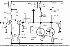
But there`something that may be good to inform....the class A amplifier and the class AB amplifier in separated sketches to easy understanding.
...........................................
There are two amplifiers superimposed in GEM diagram.
I have tried to separate and produce a sketch of the class A unit, the one will
drive current always, and will be important corrector of crossover errors..at
least, if not correct perfectly, will turn muffled the reproduction of the problems
that are resultant of crossover problems that happens in class AB amplifiers.
Dinamic crossover problems, as you normally bias class AB into condution, but…
dinamically, with the audio introduction… you will reach zero line and will
have crossover when going to the negative cicle of the waveform.
Observe that some transistors in the positive rail could be substituted by resistors
to turn more easy the understanding …. As the function is to stablish the zero volts
into the output line…working as a 50 ohms resistance.
The 47 ohms trimpot will increase the negative rail, the single ended class A output
transistor voltage, as the bigger resistance adjusted will mean bigger output transistor
base to emitter current, and this will determinate also the output off set voltage.
Also VBE multiplier was substituted by a resistor value included in the series patch
of resistors that are used to bootstrapping and to feed the needed bias current to the v
voltage amplifier transistor.
The input CCS was substituted by resistors to clear understanding off what is
under the schematic…a more simplified image of the class A, the partial output
designed by Mr. Graham Maynard.
I hope this will be usefull to a better understanding to beginners, as I was alike them
a couple of years ago..when entered the forum…as was an amplifier assembler and
an experience amplifier listener, with some expertise in A to B comparisons…blind
or not blind methods….now I can understand and design some simple units, reason why
i am trying to help other beginners
No!...my calculations are only DC, have no precision and are not something precise..
Regards,
Carlos
Attachments
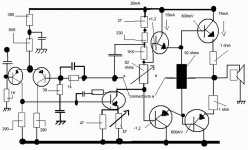
Now the AB part of his circuit..as there are two outputs, one A and other AB
This is the Class AB circuit used in the GEM, of course parts suppressed, simplified,
CCS substituted by resistor…VBE multiplier substituted by a resistor and those
things needed to have a more simple and clear vision of the AB amplifier part.
You may observe that the differential amplifier and the voltage amplifier are the
same to both Class A output circuit and Class AB output circuit…the difference to
the class Ab is that the signal, the audio voltage is taken into the Colector…when to
the single ended Class A is taken into the emitter (not shown the class A circuit here)
So, you must observe that the VBE multiplier, the bias transistor was substituted by
a resistance…because this is what the VBe multiplier is in its essence..a
variable resistance…that can have its resistance changed if receive heat from the
output heatsink….the collector to emitter resistance is reduced by heat… resistance
reduced will develop lower voltage in it`s extremes…resulting in less bias voltage
to the drivers and as consequence, to the output bases…you will see substituted
by 93 ohms adjusted resistance taken from a 100 ohms trimpot
Class AB output current normally is under 100 miliamps to each output transistor used,
in the shown case, only one output is used….so, I think that something from 10 to 100
milliamps will be enougth…. To understanding i have used 75 miliamps to output.
As those output transistor normally have gain around 100…. Only 750 microamperes will
be needed to bias the output base to emitter circuit…. As this is very small, it is used
bigger current traveling inside the driver`s collector to emitter junction…. This same current will travel over the 39 ohms resistor that will produce the needed voltage to
bias the output base….around 30 miliamps will be crossing , producing 1.2 volts, that will be 0.6 over the output line… and the -0.6 under the output line, where voltage is
Zero, and this is needed to produce Base bias to output units.
The same method is used in the 92 ohms resistor that is used to produce 2.4 volts.
beeing 1.2 volts above the output line and 1.2 volts under the output line voltage….
resulting and a potential difference of 2.4 volts…this is the needed voltage to be
developed there, to send 0,6 to the driver plus 0.6 to the output device in the positive, and also in the negative rail.
With the series resistors feeding in series the voltage amplifier collector to emitter junction, you will going reducing the voltage till you have positive 1.2 volts above the
output line (that need to be zero) and also -1.2 volts under the output line…resulting in
2.4 volts of difference of electric potential developed over the 93 ohms to produce
four times 0.6 volts…. To bias 4 transistor with 0.6 volts each one…so…4 multiplied
by 0.6 will result in 2.4 volts.
The reality is that Graham`s circuit is simple…. And normally people think it
is a hell confused…but the reason why is that it is crowdy in the schematic..filled
with many needed informs there.
Of course Graham did not explained those basic things, as in his level of
knowledge this is so basic that he may think his Dog may know…so…not
needed to explain the obvious….i am doing this hard work for him gladly.
Of course his impedance decision was clever, the use of PNP transistors in the input also, as they usually have better gain than NPN
The suppression of rail resistors to have more driven voltage,substituting that
needed voltage stabilizing resistor and capacitor to a enormous electrolytic condenser
that may hold the work as good as the resistor that can separate, a little, the supply
voltage that may variate in the output transistors, related to the first and second
transistors.
Some resistor to correct phase were used, and a modified CDom…. modified
Miller capacitor that now is alike a Snubber… capacitor in series with resistor, as
suggested last year by Eva.
Well..i am near the end of my self ordered mission…. Will rest only to show
the Graham`s arguments related the use of those special resistors and compensa
tion circuits that were suppressed in this simplified schematic.
Sorry, my word program is a little bit crazy..also sorry the English.
regards,
Carlos
Attachments
Really sorry Anatech..really i could not understand you meaning
But i believe it is some king of kindness from you.
I am completing my self ordered mission...here is Graham`s infomations that i type once again...because once one of the threads i had was moved because i have used other guy text.
This is what i have heard from Graham:
The class-A can operate at any level of output swing to counter class-AB crossover distortion.
A choke or transistor current source may be used for the class-A upper load.
Graham GEM builds do not oscillate at all !!!
Non Toshiba transistors might need additional C.dom stabilisation at the VAS. ( as indicated at 470 ohms plus 100pF in series)
Lengthy power wires to the heatsink need small 1uF bypass to the heatsink ground from each of the class-AB device collectors.
WasI added a 27k NFB resistor from the output terminal to the VAS base.
This additionally reduces open loop phase shift caused by the C.dom
This resistor allows local output stage NFB to control the composite A//AB activity, whilst reducing closed loop NFB control that would otherwise be necessary by the differential stage via the global loop.
In order that the differential stage output does not become imbalanced by the output stage's local NFB, I had to add another 27k resistor to the other differential output.
Combined, these resistors also limit plus noise added differential gain.
Without the 27k at the differential stage the amplifier still works fine, but there is a slight start-up thump.
Overall this means that when the amplifier is actively controlling loudspeaker generated back-EMF, the output stage automatically does some of the work by itself. As a result the damping is phase linear to 20kHz, which very very few other designs achieve The JLH class-A being one; and the 1970's Nelson Pass class-A being another.
Informations re writen from Graham mail.
regards....mission completed!
Carlos
Hi Carlos,
What I mean is that you can answer questions and explain this to newer members who need technical help.
I do not expect you to defend this amplifier or answer detailed questions from experienced members.
In other words, you can promote this amplifier, keep it under your wing. Explain to people starting out.
I think you can do this
-Chris
Yes...i am able to help the starting guys only
And this was the reason i decide to post something.
But of course, nothing precise, and maybe something not exactly correct...hehe.... maybe people will send bombs on me.
Hummmmm, not fair, i am behaving with good will.
Please...missiles Katiucha go away!
regards,
Carlos
And this was the reason i decide to post something.
But of course, nothing precise, and maybe something not exactly correct...hehe.... maybe people will send bombs on me.
Hummmmm, not fair, i am behaving with good will.
Please...missiles Katiucha go away!
regards,
Carlos
Attachments

- Status
- Not open for further replies.
- Home
- Amplifiers
- Solid State
- Incredible quality amplifier by Graham, prepare your ears for it