I don't mind to try.... I can allways take conclusions of that.
That's why I first tried the Snubber v1.0 😉
Yes, I lost time, a few cents but I got my conclusions 😀
I have no conclusion about your new unregulated PSU, I have not tried.
But I will try it as you design it and than compare it with a different capacitor order(big to small) 😎
That's why I first tried the Snubber v1.0 😉
Yes, I lost time, a few cents but I got my conclusions 😀
I have no conclusion about your new unregulated PSU, I have not tried.
But I will try it as you design it and than compare it with a different capacitor order(big to small) 😎
Re: Here comes the Gang
Hi Carlos,
For the 4K75 / 221 feedback res are used and Cin = 2.2UF, I now have only 47K and 100K for R1 on hand. Which one should I go for making it as a power amp? Will the DC offset worse?
carlosfm said:
Also, if you change R1 (15k) for a 10k resistor, DC-offset will be a little lower, at around 25mv.
I used 15k because I had some good 2.2uf caps I wanted to use.
Hi Carlos,
For the 4K75 / 221 feedback res are used and Cin = 2.2UF, I now have only 47K and 100K for R1 on hand. Which one should I go for making it as a power amp? Will the DC offset worse?
Re: Re: Here comes the Gang
None.
Much worse.
Unuseable.
nina said:For the 4K75 / 221 feedback res are used and Cin = 2.2UF, I now have only 47K and 100K for R1 on hand. Which one should I go for making it as a power amp?
None.
nina said:Will the DC offset worse?
Much worse.
Unuseable.
carlosfm said:100R+100nf after the bridge?
Great...
I am optimizing the values.
I made a "copy --> paste" from the Mallory QUENCHARC

BTW, do you do "something" with the trafo cable or it's not important for you ?
I think if you do a "trick" with the trafo cable you will not need big resistance values after the bridge 😀
I think if you do a "trick" with the trafo cable you will not need big resistance values after the bridge 😀
XELB said:BTW, do you do "something" with the trafo cable or it's not important for you ?
I think if you do a "trick" with the trafo cable you will not need big resistance values after the bridge 😀
I cross each secondary wires, but what does that has to do with resistance after the bridge?
You can also pass the wires around a ferrite, I did that on some PSUs.
I also cross the secondary wires.
But there is something that you also can do 😉
Try do give a few turns(20) with a diameter of 1cm
in the primary cable.
Then, do the same for the secondary.
Have you heard of this ?
Edit:
I see that you have edit your post 😉
But there is something that you also can do 😉
Try do give a few turns(20) with a diameter of 1cm
in the primary cable.
Then, do the same for the secondary.
Have you heard of this ?
Edit:
I see that you have edit your post 😉
carlosfm said:There are advantages in using very low value resistors, and also with (consistently) manageable DC-Offset, so that the Ci cap can be discarded.
It works, it's simple, it sounds very good.
Even without matching impedances (because I use very low values, and the amp would need a buffer), DC-offset is around 30mv.
Hi Carlos,
Just wonder why the datasheet say the feedback Res should be large 10K-100K. However, I had done a quick experiment using metal film res 2.21 / 100 ( 0.5W), Rin 22K and Cin 4.7UF. The sound seems to be much sharper & more focus, particularly at HF. Sharp but lack of ambience (?!). Sound like I am listning in the 'dead' room.
Will using the 1-2W carbon film help it better?
Re: Re: Improving the Non-Inverting chipamp
Are you using a preamp?
Rin should be lower (10~15k), and you should ideally have a buffer or gainstage after the pot.
Also, what PSU are you using?
loong said:Hi Carlos,
Just wonder why the datasheet say the feedback Res should be large 10K-100K. However, I had done a quick experiment using metal film res 2.21 / 100 ( 0.5W), Rin 22K and Cin 4.7UF. The sound seems to be much sharper & more focus, particularly at HF. Sharp but lack of ambience (?!). Sound like I am listning in the 'dead' room.
Will using the 1-2W carbon film help it better?
Are you using a preamp?
Rin should be lower (10~15k), and you should ideally have a buffer or gainstage after the pot.
Also, what PSU are you using?
Re: Re: Re: Improving the Non-Inverting chipamp
In my system, The 1543 NOS DAC --> Pre amp is based on HEPS project 88 ( ) High Quality Audio Preamp but with LF353 and no balance control. ---> Power Amp as mentioned.
The PS is the snuberized MKII, Tranf 25-0-25. There is another 1000UF on chip.
Today I managed to get a pair of Kiwame 2W 2.2K / 100 at US$4 total. Not sure if it will help.
carlosfm said:
Are you using a preamp?
Rin should be lower (10~15k), and you should ideally have a buffer or gainstage after the pot.
Also, what PSU are you using?
In my system, The 1543 NOS DAC --> Pre amp is based on HEPS project 88 ( ) High Quality Audio Preamp but with LF353 and no balance control. ---> Power Amp as mentioned.
The PS is the snuberized MKII, Tranf 25-0-25. There is another 1000UF on chip.
Today I managed to get a pair of Kiwame 2W 2.2K / 100 at US$4 total. Not sure if it will help.
loong said:In my system, The 1543 NOS DAC --> Pre amp is based on HEPS project 88 ( ) High Quality Audio Preamp but with LF353 and no balance control.
I don't expect decent results with that... thing.

Besides the op-amp (!) choice, I suppose you used the schematic at figure 4?
Exactly as it is? Any change?
 -in for some days before taking conclusions. ok?
Update.
Finally, I had some time to make what I had on my mind to do: reduce the value of the resistors on the snubber.
So, instead of 0.47R + 47nF, I now have 0.1R + 3.3nF.
I also increased the value of the cap between the rails, from 330nF to 3.3uF. 😱
Last, and this I made some time ago, I removed the output series resistors.
These mods I recommend to everyone that uses a snubberized PSU, whatever the type.
You should use big (1,000~2,200uf) caps on the chip, as I recommended earlier, instead of 100uf.
The results?
What the hell, this is the amp that better drives my speakers ever, and I had lot of amps in my home, including Krells...
Bass is VERY tight, detail is unbelievable, everything is right. Reminds me the Halcros.
Alas, this amp is very revealing of poor source components and/or recordings.
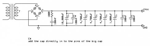
Here's the schematic, enjoy.😎
Finally, I had some time to make what I had on my mind to do: reduce the value of the resistors on the snubber.
So, instead of 0.47R + 47nF, I now have 0.1R + 3.3nF.
I also increased the value of the cap between the rails, from 330nF to 3.3uF. 😱
Last, and this I made some time ago, I removed the output series resistors.
These mods I recommend to everyone that uses a snubberized PSU, whatever the type.
You should use big (1,000~2,200uf) caps on the chip, as I recommended earlier, instead of 100uf.
The results?
What the hell, this is the amp that better drives my speakers ever, and I had lot of amps in my home, including Krells...
Bass is VERY tight, detail is unbelievable, everything is right. Reminds me the Halcros.
Alas, this amp is very revealing of poor source components and/or recordings.
Here's the schematic, enjoy.😎
Attachments

Hi Carlos!
What of resistors are you using for the 0,1R?
I`ve checked at my normal supplyers (Farnell and RS) and the only resistors they have in this low value is some hi wattage current sense resistors, mostly SMD.
It seems like normal metal og carbon film resistors under 1 ohm is almost impossible to find.
Tor Martin
Tor M said:Hi Carlos!
What of resistors are you using for the 0,1R?
Hi Tor,
They are normal 5% carbon resistors, 0.1R/1W.
Yes, they are not easy to find, I bought these some months ago (with this test in mind), on one of my regular suppliers, here in Lisbon.
They also have 3W carbon resistors, which curiously I can't find anywhere else around here too.
I find this curious, because these are bog standard, cheap parts...
Newark Electronics carries them -- look for 100mOhm -- 1/2 watt -- there's not a lot of energy flowing through that part of the circuit so 1/2 w should be fine. http://www.newark.com/NewarkWebCommerce/newark/en_US/endecaSearch/partDetail.jsp?SKU=84N2162&N=0
jackinnj said:Newark Electronics carries them -- look for 100mOhm -- 1/2 watt -- there's not a lot of energy flowing through that part of the circuit so 1/2 w should be fine. http://www.newark.com/NewarkWebCommerce/newark/en_US/endecaSearch/partDetail.jsp?SKU=84N2162&N=0
Hi!
Newark and Farnell is kind of the same firm, isn`t it?
I`ll have a closer look in Farnell`s paper catalouge and see if I have overlooked some.
tobias_svensk said:Tor, whatabout "60-619-15" @ www.elfa.se? Expensive though.
Yeah, very expensive!!
Tor Martin
- Home
- Amplifiers
- Chip Amps
- Improving the Non-Inverting chipamp