Ok. ( forget my question  )
)
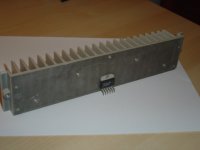
The heatsink is isolated from the rest.... I don't want a short cut
I not using a chassis, I am bulding in a wood.
Do you have any ideia to ground this decently ?
I will run my preamp with batteries, 2x 9V. (one for each Vcc)
I hope that 9V will awake the SSM2142 🙄
)The heatsink is isolated from the rest.... I don't want a short cut
I not using a chassis, I am bulding in a wood.
Do you have any ideia to ground this decently ?
I will run my preamp with batteries, 2x 9V. (one for each Vcc)
I hope that 9V will awake the SSM2142 🙄
You have already got the answer (V-) but I also recommend that you take a peek in the datasheet and the AN-1192. Both those documents contains surprisingly much.XELB said:Can any one tell me if the back of the Lm3886 is ground or V- ? 😕
As some sort of summery: What was the real improvement? Adding a resistor at the output?
I will run the chips without any resistor in the output...
I will do the same with the input and control the DC offset in the preamp.
I want to match the values of resistor, etc.. with my speakers and cables. 😉
I will do the same with the input and control the DC offset in the preamp.
I want to match the values of resistor, etc.. with my speakers and cables. 😉
XELB said:I will run the chips without any resistor in the output...
I will do the same with the input and control the DC offset in the preamp.
I want to match the values of resistor, etc.. with my speakers and cables. 😉
I'm going to the beach.
You should do the same.
Think a little more, it pays.
😎
I think I will go see the game of Portugal 😉
After drinking a few beers, I think I will be in the mood to think about that 😛
If you are going to the beach, pay attention for me to the Bikini girls 😎 LOL 😉
After drinking a few beers, I think I will be in the mood to think about that 😛
If you are going to the beach, pay attention for me to the Bikini girls
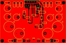
😎 LOL 😉My LM3886 PCB ( positive input )
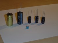
For each Vcc:
1,000uF + 1,000uF + 220uF + 220uF + 220uF + 5x 100nF ( one cap in the pin chip)
I can also use 330uF( Low ESR caps ) instead of 220uF
In red, top layer and in green, the bottom layer 😉
What do you guys think ?
For each Vcc:
1,000uF + 1,000uF + 220uF + 220uF + 220uF + 5x 100nF ( one cap in the pin chip)
I can also use 330uF( Low ESR caps ) instead of 220uF
In red, top layer and in green, the bottom layer 😉
What do you guys think ?
Attachments
I just could find a capacitor of 330pF to connect +In to the -In of the LM3886 chip.
( I have it in plastic and ceramic )
Which one should I use and what are the problems due to 330pF instead of 330pF.
( I have it in plastic and ceramic )
Which one should I use and what are the problems due to 330pF instead of 330pF.
XELB said:Which one should I use and what are the problems due to 330pF instead of 330pF.
330 or 330 is the same.😀
300 or 330pf doesn't make much difference on that position.
You can use the film cap.
I use styroflex.😉
carlosfm said:Are you sure you wanna do that?
Whatever...
It's bad this way ?
Why do you think I should not do this way ? ( an advice are allways welcome)

Is true that the LM3886 like low impedance caps near "him"?
If so, should try to low impedance as much as possible and at the same time get a good capacitance(2,2000~10,000uF) for each Vcc ?
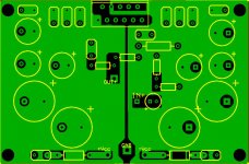
I made new improvements to my PCB.
1- the input is now perpendicular to the output (in the old version they were parallel)
2- since I building a bridged LM3886, now the ground and +/-Vcc are shared.
(but I will maintain the same capacitance as it was two different boards)
What do you guys think about it ?
If so, should try to low impedance as much as possible and at the same time get a good capacitance(2,2000~10,000uF) for each Vcc ?
I made new improvements to my PCB.
1- the input is now perpendicular to the output (in the old version they were parallel)
2- since I building a bridged LM3886, now the ground and +/-Vcc are shared.
(but I will maintain the same capacitance as it was two different boards)
What do you guys think about it ?
XELB said:Is true that the LM3886 like low impedance caps near "him"?
If so, should try to low impedance as much as possible and at the same time get a good capacitance(2,2000~10,000uF) for each Vcc ?
You should know better by now.
If you use a (separated?) snubberized PSU, things will not be too bad.
But that frenetical bypassing is not beneficial, as you have long traces which generate inductance.
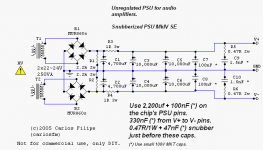
I would use a 1,000~2,200uf cap, bypassed with 100nf and snubberized, on the chip. As you know.
But maby you have another secret formula.

carlosfm said:
But maby you have another secret formula.
Yes, but I will not tell, even if you ask 😀 😀
Joke 😉
I Know that capacitor with large capacitance doesn't work very well in high frequencies. They need to be helped buy a small capacitor such as the 100nF. (this normally do the trick)
My ideia is that, near the chip we should pay more atention to the high frequencies.
(Try to get the juicy and beloved high frequencies with lot of detail)
That's why I use large capacitors(read it large capacitance) in the back and small ones in the front.
( I know you do the opposite in your PSU )
XELB said:My ideia is that, near the chip we should pay more atention to the high frequencies.
(Try to get the juicy and beloved high frequencies with lot of detail)
The snubber does that.
Lots of paralleled caps don't.
XELB said:That's why I use large capacitors(read it large capacitance) in the back and small ones in the front.
( I know you do the opposite in your PSU )
No, I don't.
I'ma gonna smackah u face. (c) Jocko
😎
Attachments
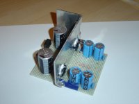
You use 4,700uF + 10,000uF + 10,000uF , correct ?
If I were you I would do it like this :
10,000uF + 10,000uF + 4,700uF 😉
Big capacitance in the back 😛
I once tried 4,700uF + 4,700uF + 18,000uF and then 18,000uF + ......
Now I use the second choice. 🙂
If I were you I would do it like this :
10,000uF + 10,000uF + 4,700uF 😉
Big capacitance in the back 😛
I once tried 4,700uF + 4,700uF + 18,000uF and then 18,000uF + ......
Now I use the second choice. 🙂
XELB said:10,000uF + 10,000uF + 4,700uF 😉
You need more capacitance after the resistor.
And it's better to parallel same value caps.
If you want more capacitance you can parallel a third 10,000uf cap, or just use two 22,000uf paralleled caps per rail.
What you are trying to do with the 4,700uf cap paralleled with the 10,000uf doesn't work as you think.
You have a snubber there to lower the impedance.
That paralleled 4,700uf cap doesn't do much.
Btw bass is gorgeously tight, dynamics to hold your breath.
Transparency is there at the buckloads.
But this is all subjective talk.😎
Nobody can stop you from trying what you want.
I'm just advicing you, because in that way you are spending time and money.
- Home
- Amplifiers
- Chip Amps
- Improving the Non-Inverting chipamp