I've put it in my backlog
You should not build the Tringlotron amp. I am quite sure the inductor loaded SLAPS and XSLAPS designs sounds much better reproducing music.
The Tringlotron was just to show that there is a reasonable simple way to test simple single ended amps based on true feed forward error correction. Some people don´t want to wind large, heavy and expensive bifilar coils, and the Tringlotron is a way to bypass this.
If you are bored during Covid1984 lockdowns and have nothing else to do, then by all means build a Tringlotron. You have to be quite careful with routing cables and components since it will grab any excuse to oscillate with both hands immediately. I would guess it needs some high frequency compensation to tame the high frequency behavior to avoid oscillation with a reactive load.

To much feed forward evil corruption creates a demonic sound.
Measurements on SLAPS for bass, that's SLAPS with IRFP150 and +/- 24 power supply versus the corresponding X-SLAPS.
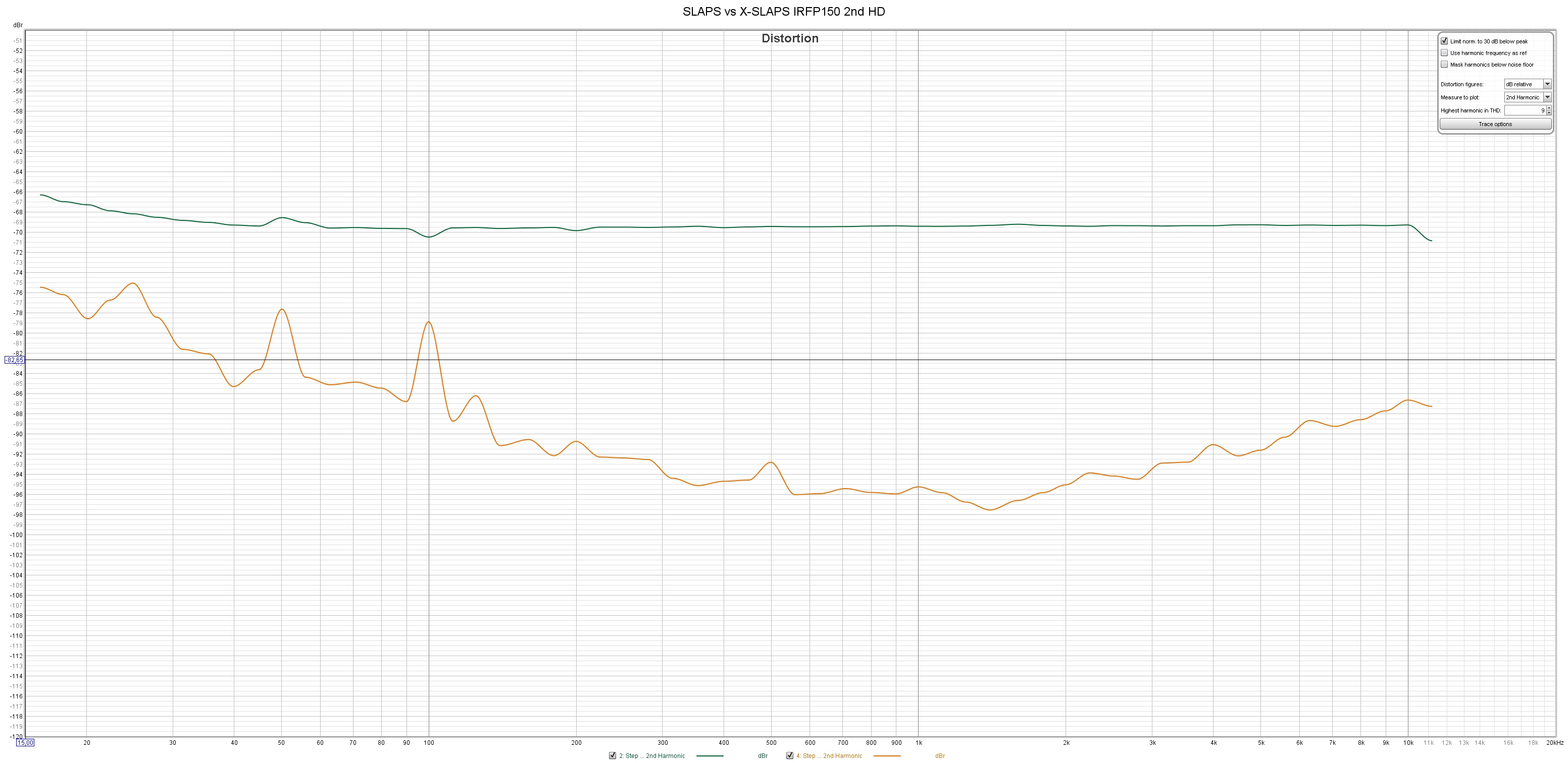
SLAPS (green) vs X-SLAPS (orange) IRFP150 2nd HD at 1 W:
Huge improvement, almost 30 dB at some frequencies!
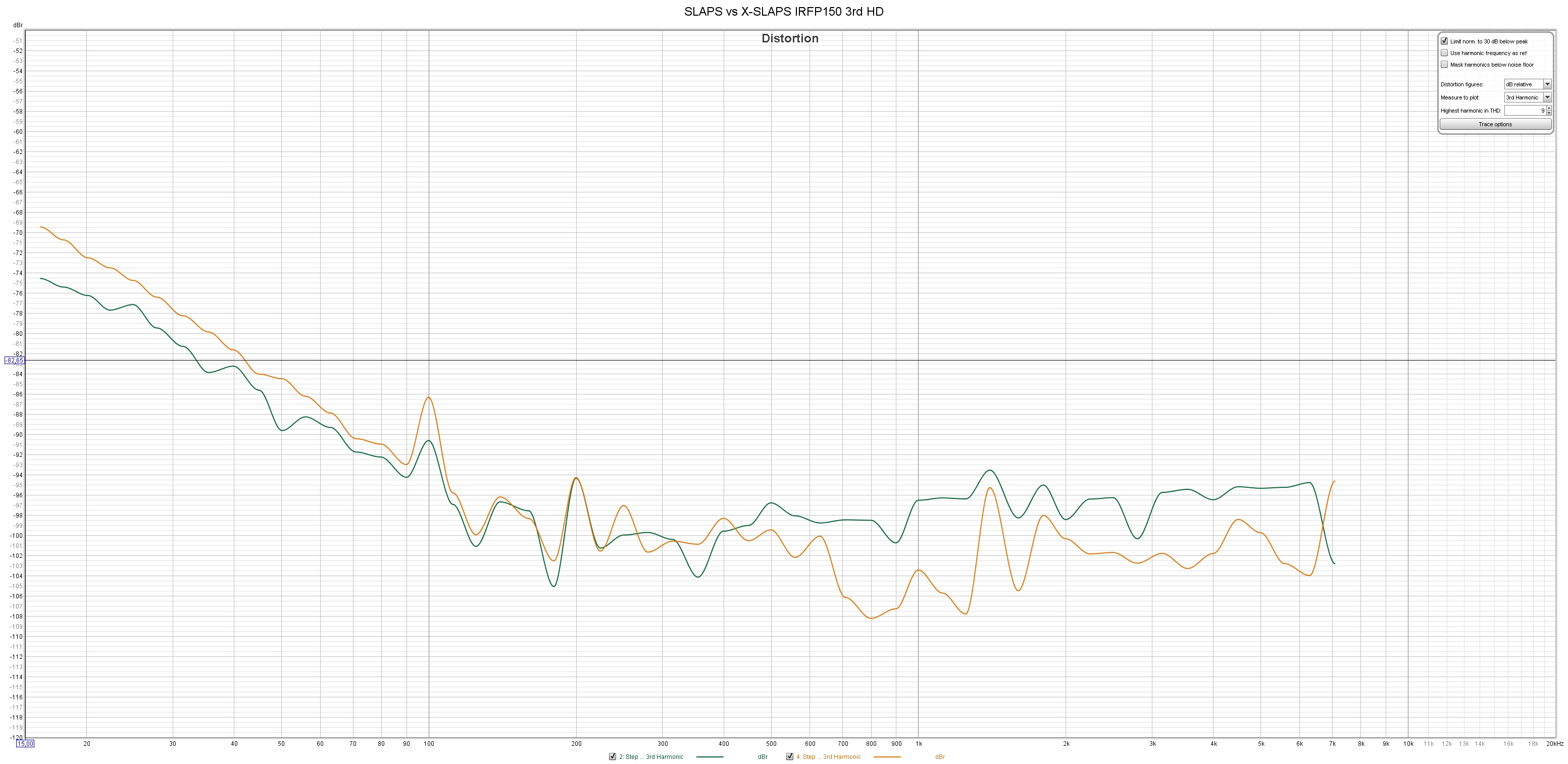
SLAPS (green) vs X-SLAPS (orange) IRFP150 3rd HD at 1 W:
Not that much difference as for the 2nd HD but still significant, at least over 200 Hz.
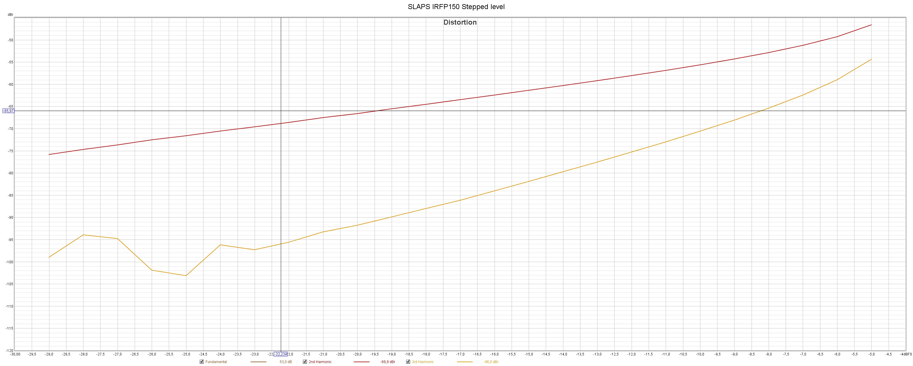
SLAPS IRFP150 Stepped level at 1 kHz (2nd HD red, 3rd HD orange), from input level -29 dB (0.25W) to -5 dB (64 W):
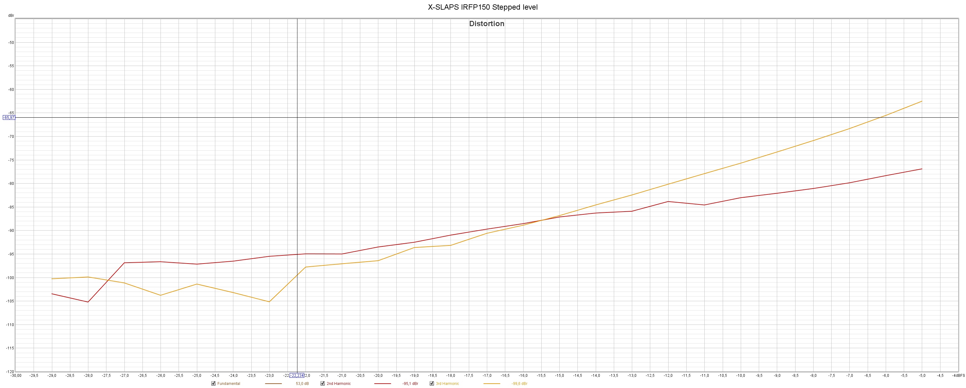
X-SLAPS IRFP150 Stepped level at 1 kHz (2nd HD red, 3rd HD orange), from input level -29 dB(0.25W) to -5 dB (64 W):
Inaudible (well, that could be disputed) levels (-62 dB) of 3rd HD at 64 W!
With no NFB!
This time I haven't tried to match the MOSFETs on one side against the other side.
So it might get even better.
Why do I want them to perform better?
One reason is to be able to lower the bias to let the heat sinks be a little less hot.
The above measurements were made at an Id of 800 mA.
I'll test at 500 mA now.
SLAPS (green) vs X-SLAPS (orange) IRFP150 2nd HD at 1 W:
An externally hosted image should be here but it was not working when we last tested it.
Huge improvement, almost 30 dB at some frequencies!
SLAPS (green) vs X-SLAPS (orange) IRFP150 3rd HD at 1 W:
An externally hosted image should be here but it was not working when we last tested it.
Not that much difference as for the 2nd HD but still significant, at least over 200 Hz.
SLAPS IRFP150 Stepped level at 1 kHz (2nd HD red, 3rd HD orange), from input level -29 dB (0.25W) to -5 dB (64 W):
An externally hosted image should be here but it was not working when we last tested it.
X-SLAPS IRFP150 Stepped level at 1 kHz (2nd HD red, 3rd HD orange), from input level -29 dB(0.25W) to -5 dB (64 W):
An externally hosted image should be here but it was not working when we last tested it.
Inaudible (well, that could be disputed) levels (-62 dB) of 3rd HD at 64 W!
With no NFB!
This time I haven't tried to match the MOSFETs on one side against the other side.
So it might get even better.
Why do I want them to perform better?
One reason is to be able to lower the bias to let the heat sinks be a little less hot.
The above measurements were made at an Id of 800 mA.
I'll test at 500 mA now.
You should not build the Tringlotron amp. I am quite sure the inductor loaded SLAPS and XSLAPS designs sounds much better reproducing music.
The Tringlotron was just to show that there is a reasonable simple way to test simple single ended amps based on true feed forward error correction. Some people don´t want to wind large, heavy and expensive bifilar coils, and the Tringlotron is a way to bypass this.
If you are bored during Covid1984 lockdowns and have nothing else to do, then by all means build a Tringlotron. You have to be quite careful with routing cables and components since it will grab any excuse to oscillate with both hands immediately. I would guess it needs some high frequency compensation to tame the high frequency behavior to avoid oscillation with a reactive load.
View attachment 904906
To much feed forward evil corruption creates a demonic sound.
Item is removed from the backlog.
So I'm finished
 with the evaluation of X-SLAPS (for now).
Next step will be design the X-SLAPS' box and then build a bunch.
Along with serious matching of course.
Impressive results!!! 🙂
An upward of 30 dB improvement in second harmonics is quite impressive. The original SLAPS for bass does have nice performance to start with.

Thanks for doing all these measurements and posting them here!
An upward of 30 dB improvement in second harmonics is quite impressive. The original SLAPS for bass does have nice performance to start with.
Thanks for doing all these measurements and posting them here!
Impressive results!!! 🙂
An upward of 30 dB improvement in second harmonics is quite impressive. The original SLAPS for bass does have nice performance to start with.
Thanks for doing all these measurements and posting them here!
And I say thanks for the ingenious designs
 .
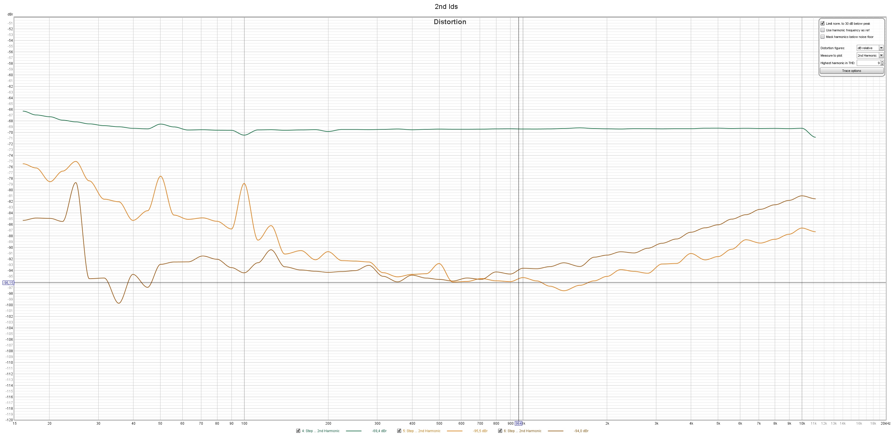
.Here are the measurements with X-SLAPS at Id 500 mA:
(Teal is SLAPS an 800 mA, orange is X-SLAPS at 800 mA and brown is X-SLAPS at 500 mA)
2nd HD:
An externally hosted image should be here but it was not working when we last tested it.
A little less at Id 500 mA than at 800 mA for X-SLAPS
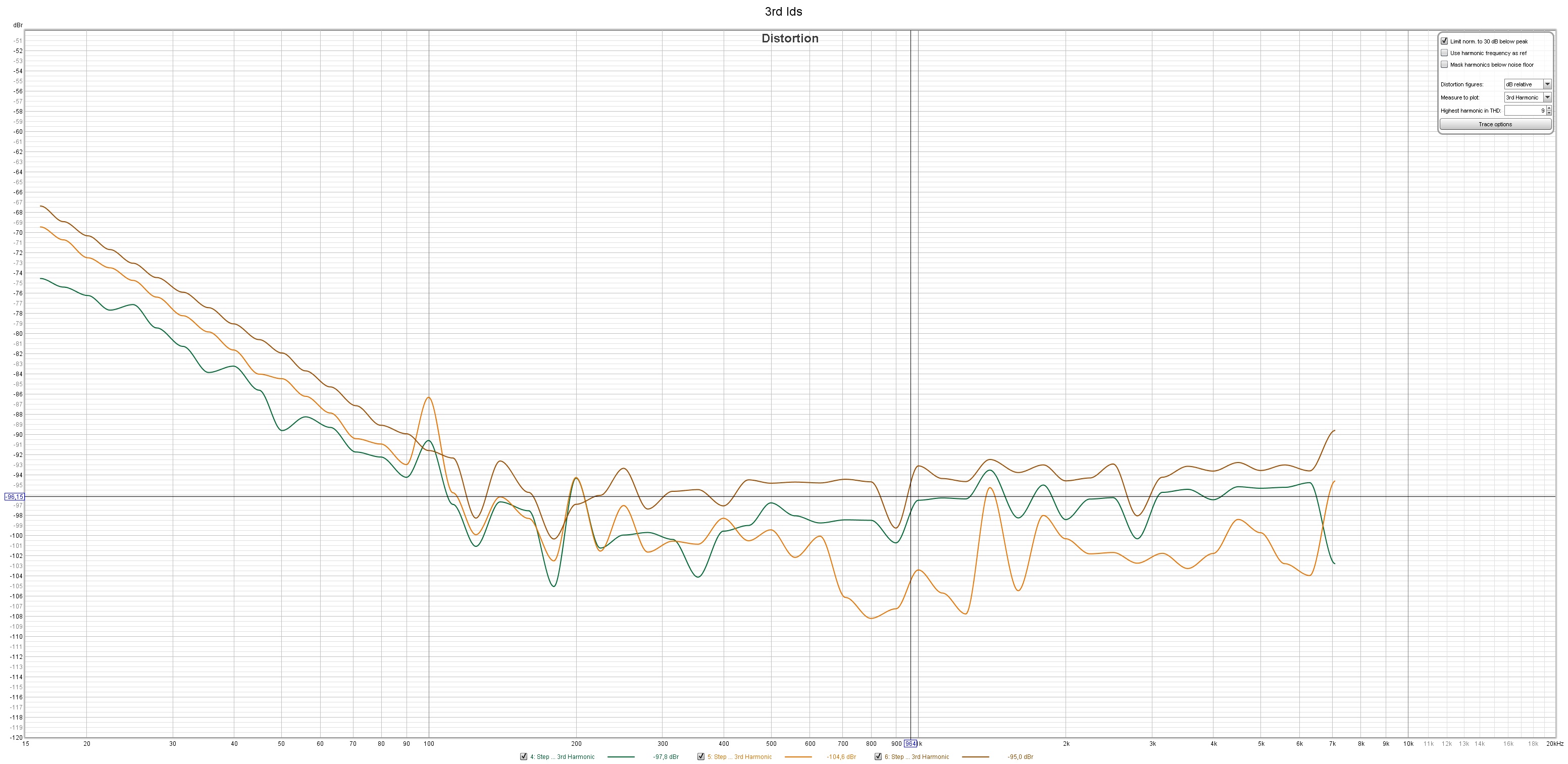
3rd HD:
An externally hosted image should be here but it was not working when we last tested it.
Here the lesser Id for X-SLAPS means higher 3rd than for even the SLAPS.
3rd HD is unaffected by the cross connection and depends more on the current.
As expected.
Sorry, no progress with the X-SLAPS.
Been busy digging and installing municipal water and sewage and a central heating system based on rock heat.
It's nice to be able to listen to music without worrying that the electric heaters trips the fuses.
Ten SLAPS draw an awful lot of current
As the warmer part of the year approaches, I really need the X-SLAPS so I don't need to install an AC as well; lowering the idle current is the main goal with X-SLAPS.
But right now I'm busy with my second generation of the plasma CNC, which is also needed for X-SLAPS manufacturing.
Time to execute this project.
It was doable to have the prototype on the lab bench, but having twenty SLAPS coils in my music room requires any better solution.
One thought is to have separate units with power supplies and SLAPS coils and separate amplifier for every X-SLAPS.
The former can then be hidden behind the woofer and subwoofer cabinets.
To interconnect the two parts (that is: two times drain and source) I was thinking of using five pin stove plugs and outlets.
I must also have negative supply and earth for the bias.
The amplifiers, that more or less are heat sinks, will be a rack on each side.
Perhaps like one giant 60x45 cm heat sink.
A ten channel differential preamplifier has to be built as well.
I'll be using four pin GX12 connectors as interconnection between preamplifier and amplifier .
RCA cables to the DAC of course.
So a meter of cable between the power supply and SLAPS coils and the amplifier should be feasible; it is rather low impedance.
What do you think?
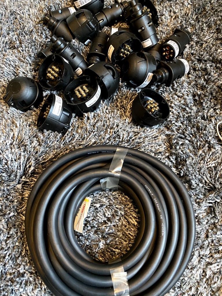
A seven pole trailer connection is better and cheaper.To interconnect the two parts (that is: two times drain and source) I was thinking of using five pin stove plugs and outlets.
I must also have negative supply and earth for the bias.
The pins are specified up to 2,5 square millimeters and I will also have room for the supply for the bias.
I have used that cable, though not the trailer connectors, extensively for umbilicals between PSUs and amps ... together with some military style locking multipin connectors ...
Conceptual box for the X-SLAPS amplifier part:
This is X-SLAPS for bass, X-SLAPS for SLAM! is half the height.
The heatsink will be mounted in the back.
Hopefully I will succeed in welding something like this, the front mesh will of course be detachable.
There will be some holes for the cable to the SLAPS/PSU box, the pre-amplifier contact socket and the speaker cables.
The layout for X-SLAPS for bass:
There will only be two IRFP150 per heatsink. The source resistor will be mounted where the center FET:s are, so they will be mounted directly to the heatsink.
There will also be two input cards as X-SLAPS must have differential input signals.
The layout for X-SLAPS for SLAM!:
Here the center IRFP044 will be replaced by the source resistors and there will be two input cards as well.
An externally hosted image should be here but it was not working when we last tested it.
This is X-SLAPS for bass, X-SLAPS for SLAM! is half the height.
The heatsink will be mounted in the back.
Hopefully I will succeed in welding something like this, the front mesh will of course be detachable.
There will be some holes for the cable to the SLAPS/PSU box, the pre-amplifier contact socket and the speaker cables.
The layout for X-SLAPS for bass:
An externally hosted image should be here but it was not working when we last tested it.
There will only be two IRFP150 per heatsink. The source resistor will be mounted where the center FET:s are, so they will be mounted directly to the heatsink.
There will also be two input cards as X-SLAPS must have differential input signals.
The layout for X-SLAPS for SLAM!:
An externally hosted image should be here but it was not working when we last tested it.
Here the center IRFP044 will be replaced by the source resistors and there will be two input cards as well.
Layout for a SLAPS/PSU box:
This box will weigh well over 20 kg, so it must be very sturdy.
My first thought was to have a plywood bottom and then screw steel sides to it. But I doubt it'll hold.
I'll add a steel girdle to every SLAPS coil. It will increase the inductance but more important decrease the magnetic leakage fields.
And that will be important as there will be two SLAPS coils in every X-SLAPS box.
An externally hosted image should be here but it was not working when we last tested it.
This box will weigh well over 20 kg, so it must be very sturdy.
My first thought was to have a plywood bottom and then screw steel sides to it. But I doubt it'll hold.
I'll add a steel girdle to every SLAPS coil. It will increase the inductance but more important decrease the magnetic leakage fields.
And that will be important as there will be two SLAPS coils in every X-SLAPS box.
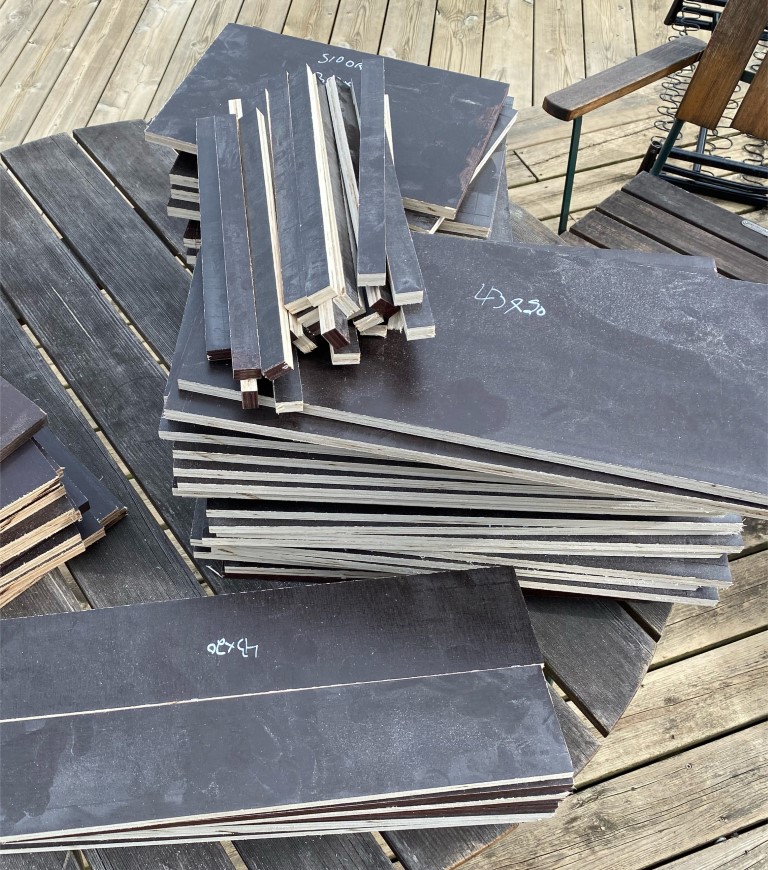
I already have eleven SLAPS coils but I need twenty for the ten X-SLAPS I intend to build.
So I had to make nine more coil formers and twenty girdles:
Measuring a SLAPS coil at 100 Hz with an UT611 gives one more mH with a girdle:
So I had to make nine more coil formers and twenty girdles:
An externally hosted image should be here but it was not working when we last tested it.
Measuring a SLAPS coil at 100 Hz with an UT611 gives one more mH with a girdle:
An externally hosted image should be here but it was not working when we last tested it.
I cut some plywood for the coil boxes:
Sturdy handles is a must, these are sold by Thomann
The sturdy handles are really needed when the a finished coil box weighs more than 27 kg:
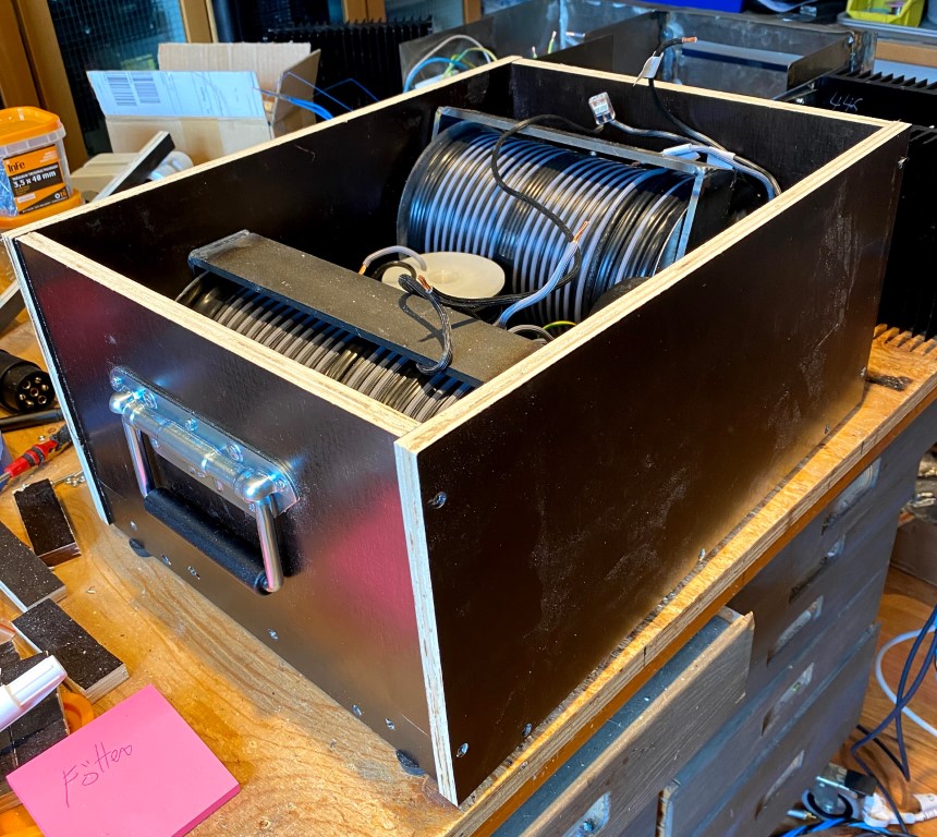
I made cradles for the SLAPS coils with room for the girdle::
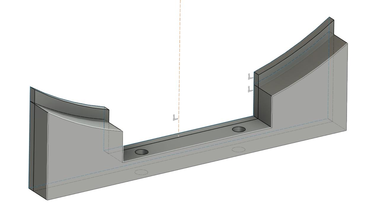
So there's two cradles per SLAPS coil, a total of four for each box.
Together with 75 cm cable ties to anchor them down, they worked really well.
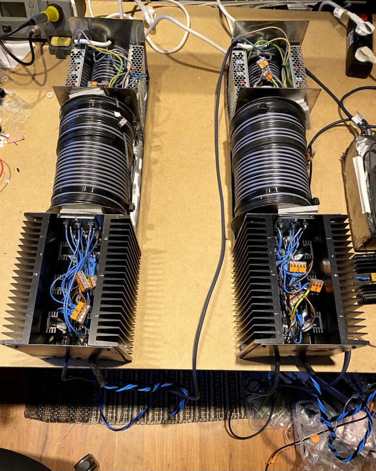
This is a finished "Dual SLAPS coils, +/-24V":
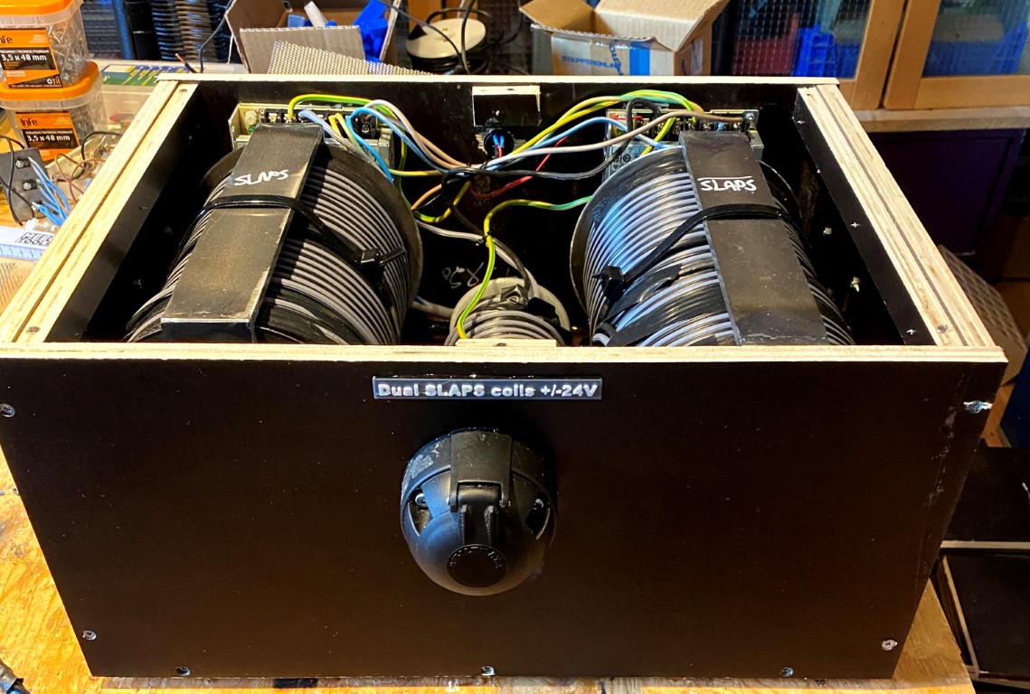
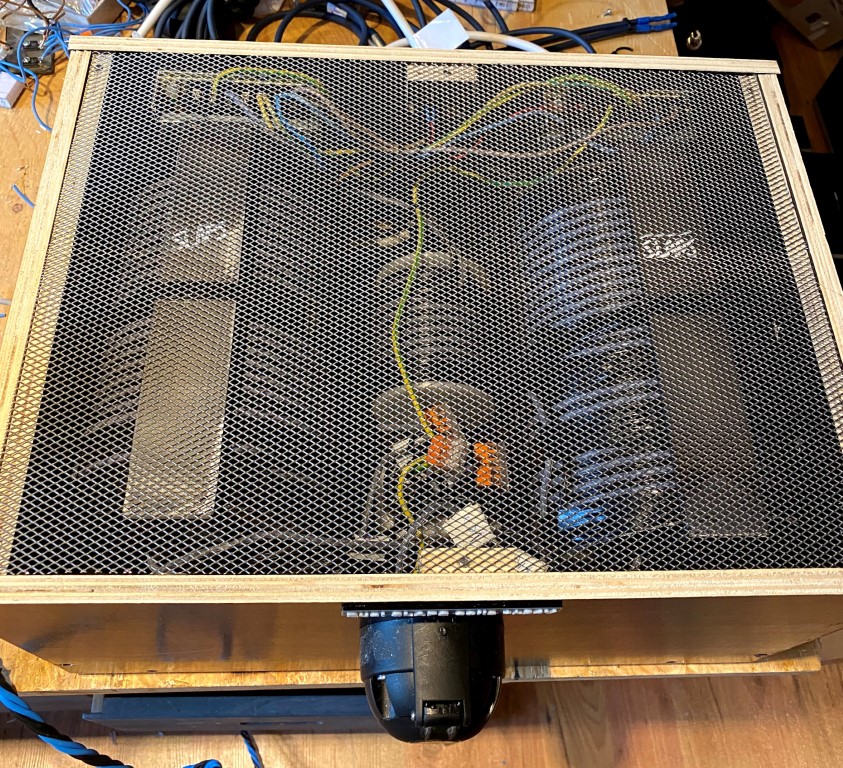
from above:
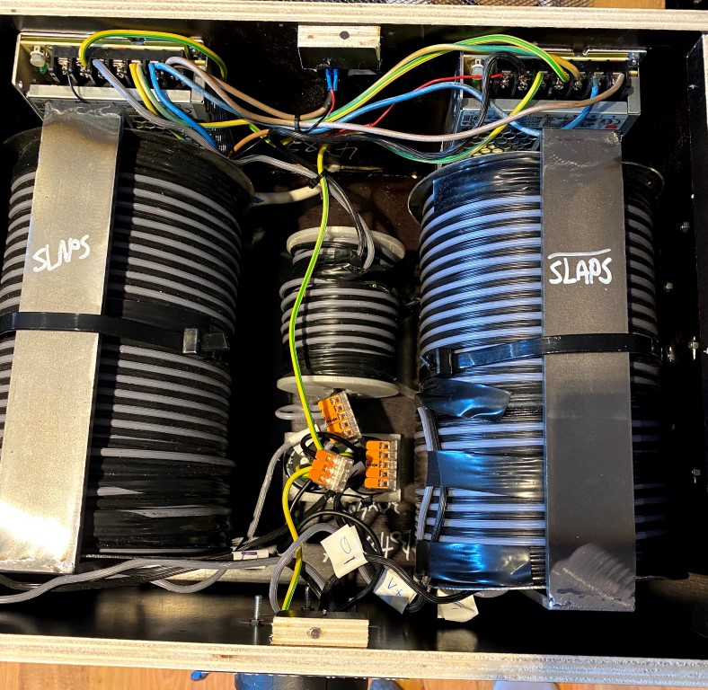
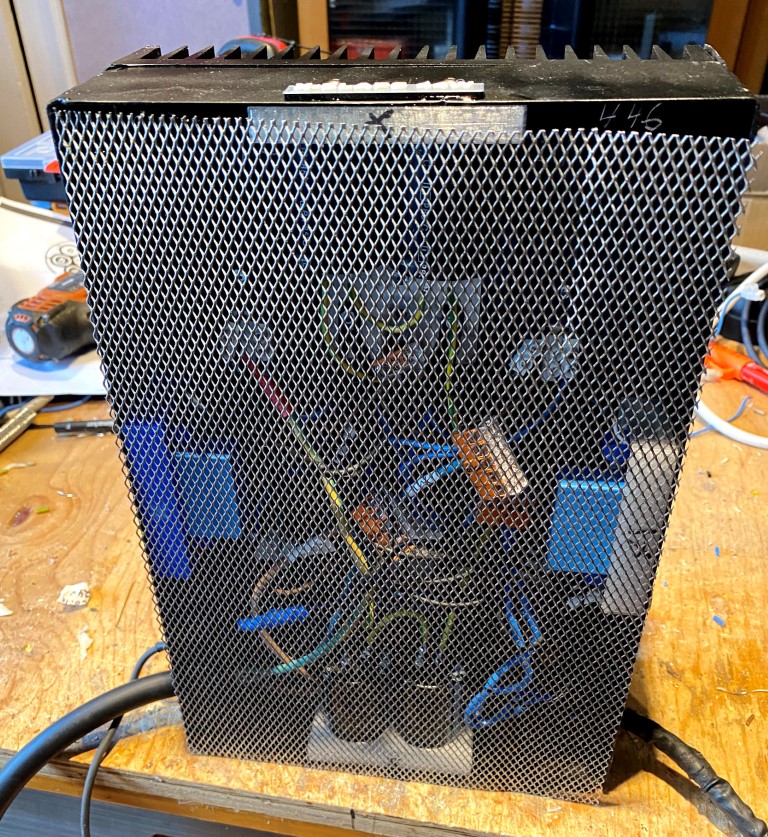
Countersunk magnets keeps a grid in place,
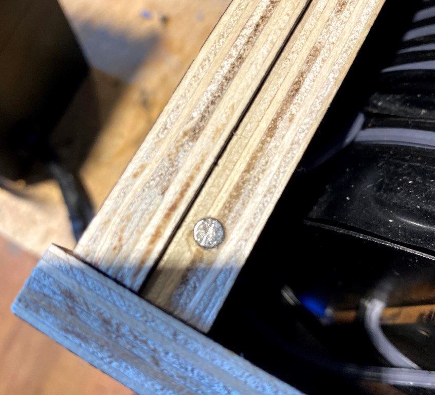
like this
It's two IRFP150 per side i the 44W variant (X-SLAPS for bass):
The only differences for the 4W variant (X-SLAPS for SLAM!) are that the power supply is +/-12V and that the MOSFETs are IRFP044.
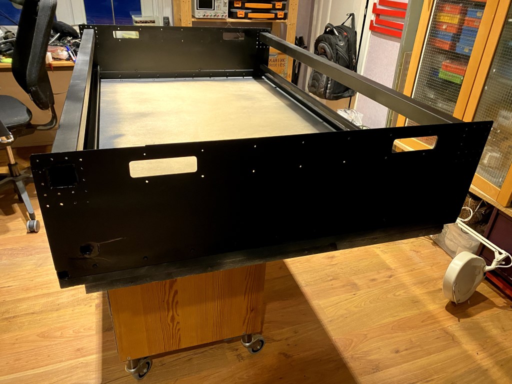
A simple steel frame around the two heat sinks make a box for the active parts:
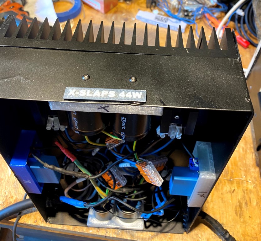
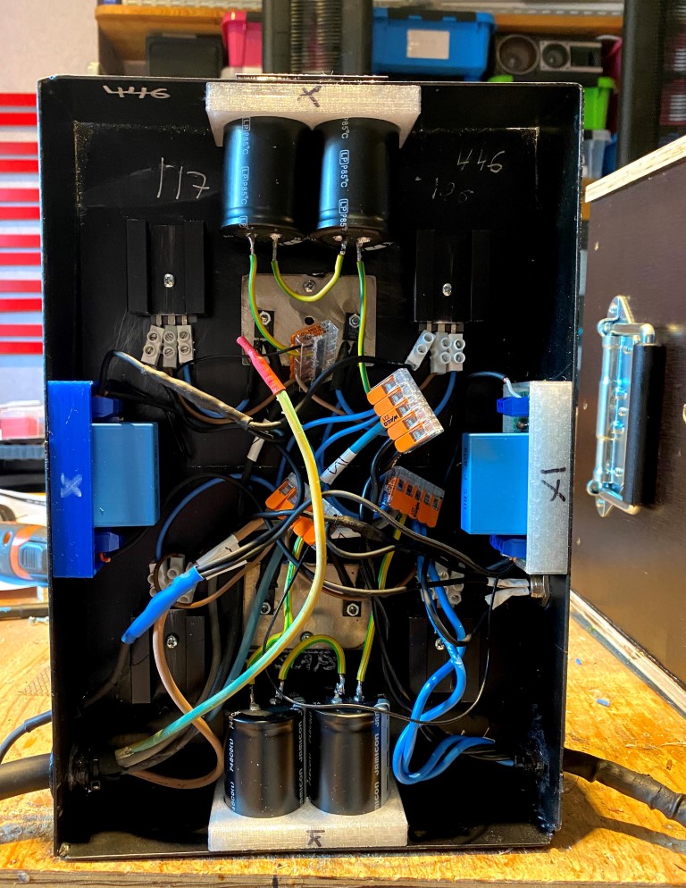
There will be a grid in front of these to:
Weighs only 5,2 kg:
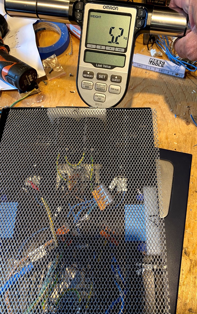
So a complete X-SLAPS (27,2 + 5,2 kg) has a little bit more than one watt per kilogram.
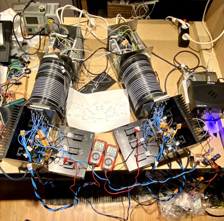
Before the series production, I must test this prototype and check if two less IRFP150 have made any difference when it comes to current consumption and reactive power
while still exceeding the single SLAPS performance.
Sturdy handles is a must, these are sold by Thomann
The sturdy handles are really needed when the a finished coil box weighs more than 27 kg:
I made cradles for the SLAPS coils with room for the girdle::
So there's two cradles per SLAPS coil, a total of four for each box.
Together with 75 cm cable ties to anchor them down, they worked really well.
This is a finished "Dual SLAPS coils, +/-24V":
from above:
Countersunk magnets keeps a grid in place,
like this
It's two IRFP150 per side i the 44W variant (X-SLAPS for bass):
The only differences for the 4W variant (X-SLAPS for SLAM!) are that the power supply is +/-12V and that the MOSFETs are IRFP044.
A simple steel frame around the two heat sinks make a box for the active parts:
There will be a grid in front of these to:
Weighs only 5,2 kg:
So a complete X-SLAPS (27,2 + 5,2 kg) has a little bit more than one watt per kilogram.
Before the series production, I must test this prototype and check if two less IRFP150 have made any difference when it comes to current consumption and reactive power
while still exceeding the single SLAPS performance.
Just stumbled into this thread and WOW!!!! Now that is some dedication to creating a monstrous amplifier. Way to go!!!
- Home
- Amplifiers
- Pass Labs
- Improving SLAPS - introducing X-SLAPS