I've found this page: LTspice Lesson 1: Generating IV curves | iExploreSiliconValley.com
but I can't plot curves of the PI. Does anyone knows how to do it?
Thanks
but I can't plot curves of the PI. Does anyone knows how to do it?
Thanks
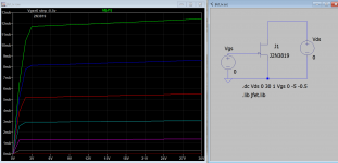
Here is how I plot IV curve for jfet 2n3819 or any one from jfet.lib.
Attachments
Last edited:
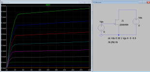
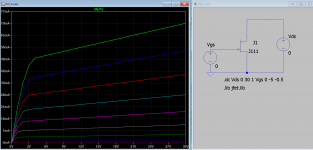
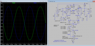
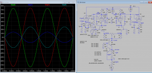
I managed to get 2n5459 (left) and J111 (right) to work but balance have to done by increasing offset of 0.5 @V2 input. Attached are the results. DC is not balanced, that is ok as there is cap blocking DC downstream anyhow.
Attachments
Thank you Koonw, tonight I will try to get the loadlines as you suggested.
This morning while having the shower, I had an idea:
what if I split the 12AT7 cathode follower resistor (47k or 150k depending on the version) in two, and I connect the grid of each 12AX7 to those points (one connection for each side)?
It shoud "ultralinear-ize" the phase inverter. Am I right?
This morning while having the shower, I had an idea:
what if I split the 12AT7 cathode follower resistor (47k or 150k depending on the version) in two, and I connect the grid of each 12AX7 to those points (one connection for each side)?
It shoud "ultralinear-ize" the phase inverter. Am I right?
Last edited:
Yes it can be done but is not as straight forward as if both are tubes. Since you have jfet at the bottom, you need to tap at much lower point so then UL% is only 10%, unless you use level shifter. But for dc wise say it's 25V at the tap, jfet drain will be set at about the same voltage via cathode of upper tube. That is what you looking for, and loadline can be more easily drawn.
Attachments
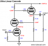
I've found the source of the image you posted: It's About Time & Ultra-Linear Line Stages
I've also found an explanation of this configuration here: The Tube CAD Journal, Hybrid Cascodes
plus similarities here: https://www.pearl-hifi.com/06_Lit_Archive/14_Books_Tech_Papers/Wright_Allan/SP-15_Article.pdf
and here: Comments on this phono preamp?
to increase the UL percentage, can we use two separate voltage dividers for the 12AX7 grids, with 10 times the impedance of CF cathode resistor, using the negative voltage of the bias power supply as a bottom reference, instead of the ground?
This way, to obtain the same +20V, the voltage divider and so the feedback will pass from 10% UL to 30% UL.
Last edited:
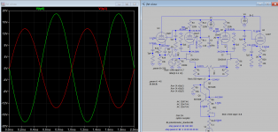
It seems it is correcting the upper tube only, so the Fet swings more.
Also, the THD seems almost identical (bit less H2 in UL).
Are there better ways to apply local feedback in this scenario?
Also, the THD seems almost identical (bit less H2 in UL).
Are there better ways to apply local feedback in this scenario?
Since if adjusting the pot has little or no effect no AC, then you only have DC to worry about, in a way this is very good if next stage is direct coupled. With this feedback the tube and nfet nearly will have same distortion as it self biased and self corrected.
Thanks you Koonw, I will try some different kinds of feedback this evening, in order to see if there's a way to improve the PI&driver. A second CSS on the drivers?
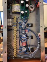
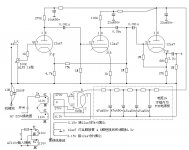
12AX7 layout
Anyone know which of these tubes is the left and the right ?
Trying to figure out because I have a pair of 12AX7 that are the same and one different. So I’d like to install the pair as left and right...
Thx
Anyone know which of these tubes is the left and the right ?
Trying to figure out because I have a pair of 12AX7 that are the same and one different. So I’d like to install the pair as left and right...
Thx
Attachments
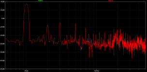
I tried cathode feedback too, but with no luck.Ok good. I have one more snapshot to share that the tubes are correcting themselves so the output stay the same.
A single CCS for both drivers is not propedeutic too.
Two CCS will probably be an improvement on the driving capability, but I've not tested yet.
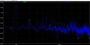
What I've seen is that with gnfb the THD can drop to 0,08% up to around 33 Wrms.
Two switchable levels of gnfb or even better a pot that can work between two fixed extremes could be a good implementation, as at low volumes I like the open sound with no gnfb, but approaching high volumes there's too much THD.
I would have preferred to apply local feedback to PI and Driver, but at least I haven't seen a good way to do it.
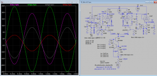
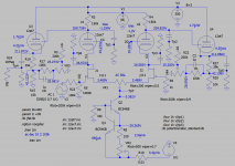
Have you tried feedback to gate of input jfet from the output from cathode follower, it's negative feedback. Haven't tried to feedback to the gate of the other jfet. With about 6db, the gain falls by half, from 100 to 50Vp, distortion drops from 1% to 0.14%. I have the UL tap, so you might get different result if you do not have it. UL drive the gain gain of jfet up and reduce the top tube gain, I need to find the best proportion, not sure on the right track or not.
Btw, the Tp in the schematic is just 0.1u/10Meg RC circuit.
Btw, the Tp in the schematic is just 0.1u/10Meg RC circuit.
Attachments
Thank you,
I thought about it, but with a volume pot at jfet gate, the feedback ratio increases when the pot is turned clockwise. I will give it a try anyway, it could be positive to have less feedback at low volumes and more at higher volumes.
I thought about it, but with a volume pot at jfet gate, the feedback ratio increases when the pot is turned clockwise. I will give it a try anyway, it could be positive to have less feedback at low volumes and more at higher volumes.
Hi Koonw,
have you tried simulating the circuit by applying feedback on half side of the PI only? Looking at your schematic: the signal enters on the left side (J1) of the PI, whilst the feedback is taken from U4's cathode and injected to J2's gate. Will it remain balanced plus will it get local feedback?
have you tried simulating the circuit by applying feedback on half side of the PI only? Looking at your schematic: the signal enters on the left side (J1) of the PI, whilst the feedback is taken from U4's cathode and injected to J2's gate. Will it remain balanced plus will it get local feedback?
- Home
- Amplifiers
- Tubes / Valves
- improvements on 12AX7 12AT7 EL34 schematic?