If you need to dampen RF stuff, you can increase C503/4 to 100pF, maybe even 150pF (polystyrol).
Or put capacitors over R507/8. 100pF will give you a ~400kHz roll-off frequency.
I haven't checked out OPA2228, but a min gain of 4-5 normally indicates a 'non-compensated opamp', so you may well need these capacitors.
As readers of this thread will know, I like the OPA2134, but OPA2604 and OPA1612 also do the job really well.
Of course, the 1612 only comes as SMD, so you'll need it on a DIP conversion pcb.
Per

R507-508 have holes where I could parallel a cap with them, should I add 100pf styro? Yes the 2228 is the uncompensated brother of 2227, never tried the 2132/34, but I am tempted to order 2 pieces,
These are some photos from couple weeks ago, since then I changed the VAS transistors from BF469/470 to C3423/A1360
So the whole list of changes as follows:
All capacitors changed where possible to Wima MKS2
Changed value of relay delay capacitor to 560uf
Filter caps changed to 2 x 22000uf CDE
Pre-amp resistors changed to new ones from vishay, zenner changed to new ones to drop voltage to 32-33V
Increased capacitors for pre amp from 470uf to 2200uf, replaced 220uf de-coupling caps to Wima 10uf
Replaced 10uf coupling caps to Wima 2.2uf
Replaced input resistor from 47K to 12K (-1.5mV/-3mV on left right channel now)
Replaced Vbe multiplier transistor to KTC3114 (it seems to be the best there is for this job, very high hfe and ft)
Bias now stabilises in about 2-3min to 8mV rock solid
Replaced output transistors to Sanken C6011
Replaced drivers first to C4793 but then to C5171
Replaced also pre amp stabilisation transistors and relay transistor
Also replaced VAS resistors from 100R to 330R
Also input cap changed from 330pf to 100pf styro
Also emitter resistors changed to 0.10R from 0.22R
Added opamp sockets
I will add more recent photos tomorrow
Maybe I missed some changes 😅
Edit: NFB cap changed to 270uf hybrid
Also replaced bananna connectors to the gold plated ones Rotel uses on the new models
In total there are 5 hybrid polimer caps in the whole amp not counting the 4 main filtering ones, no electrolitics in the signal path 😁
Criss
Last edited:
Regarding de VAS stage, would increasing C613-616 from 220pF to 470pF help in anyway? Analising the schematic of the RA-06 they changed from 220pF to 470pF here, is it to comensate for the higher cob of the 2SD600K (30pF) they used for VAS? in RA-971 they used 2sc2910 (6pF if I remeber right) I used KEC C3423 for VAS with cob of 3pF, would upping to 470pF help anything? I have a couple of Silver Micas from CDM 470pF but no 220pF at hand, so if they will work its a win-winIf you need to dampen RF stuff, you can increase C503/4 to 100pF, maybe even 150pF (polystyrol).
Or put capacitors over R507/8. 100pF will give you a ~400kHz roll-off frequency.
I haven't checked out OPA2228, but a min gain of 4-5 normally indicates a 'non-compensated opamp', so you may well need these capacitors.
As readers of this thread will know, I like the OPA2134, but OPA2604 and OPA1612 also do the job really well.
Of course, the 1612 only comes as SMD, so you'll need it on a DIP conversion pcb.
Per
Thank you all for your time and help
Hi Chriss,
First of all, in order to "help" - there has to be an identified problem in the first place. Have you tested the stability of the amp after all your various changes?
I would put a scope on the output - first with zero volume and if ok, then apply a square wave to check for overshoot and ringing.
Per
Good day, i had a few minor issues with my RA-02 and put it down to it needing to be recapped. Main issue was the right channel sometimes loosing significant gain, turning the amp on and off fixed the issue. Otherwise i was very happy with the amp which i have had for 20 years.
Following a lot of info from these forums i recapped all the electrolytics, replaced ceramics with silver mica's in power amp section and replaced the input resistors.
However now when the amp is turned on and speaker selector is engaged there is a big pop (like high gain) through the speakers and slight hum. I'm not keen to do this much more because it sounds like hell on the speakers.
Any ideas/help to diagnose where i go from here will be much appreciated. Definitely a case of curiosity killing the cat.
Erm, you replaced the compensation cap? I think there's a small chance of oscillation from the symptoms, especially the appearance of hum (due to oscillation destroying the PSRR) and the DC offset that's clearly now present. But there are many possibilities, which is why its wise not to swap everything in one go. First step unplug speakers and measure the DC offset - I'd suggest not running the amp for long in case things are overheating.replaced ceramics with silver mica's in power amp section
The original gain issue could be various things but simple loose connection or cracked solder joint is most likely.
Thanks for the speedy reply. I originally tried the mod on P36 in this thread to a tee. Problem presented so fitted same value in links, put non polarised 10uF in 601 and 602 and 100uF polarized in 605 606. For the mod i was using 220uF non polarized on C605 and C606 and 6.8uF MKP on 601 and 602.
DC offset is at .2mV which is low. So guess i'll start by adjusting that?
DC offset is at .2mV which is low. So guess i'll start by adjusting that?
Offset is now at 4mV and same issue. The mighty pop goes through the right only then both hum. Quicky turn it off. I have double checked and triple polarity of everything replaced.
Most definitely at 4mV at the test points and on the speaker outputs with no load. I’m at a bit of a loss. Have resoldered everything in case of dry joins etc..
Well, you need to employ some good staged old fault finding. I guess that you don't have a scope?
Anyway, an offset of 4mV dc is more than respectable for an old Rotel - but what is the ac value? Both channels? If ok:
Isolate the problem by grounding one end of thumping channel's R601/02 and turn on. If the thump is still there, you have most probably narrowed the problem area to that channel's power stage. And we'll go from there.
Disclaimer: Remote fault finding is not the easiest of disciplines.....!!!
Per
Last edited:
Thank you for time and help, well, truth be told I didn't check with a scope, I only checked basic voltages/temperature of active parts with flir for hot spots, amp is playing for last month or so intro 4ohm speakers, I even test lower than 4ohms and high power for about 1hrs, max heatsink temp was about 66-70c with bias set to 8mv per manual, I am expecting a bit higher heat with the C5171 and C6011 driver/output transistors, I am asking about the caps, cause I see them upped from 220pf to 470-560pf on Rotel models with same topology that use C4793 drivers and C5200 or same D1047 as 971 default outputs, I know proper testing is best with a scope, but without one at hand, I cannotHi Chriss,
First of all, in order to "help" - there has to be an identified problem in the first place. Have you tested the stability of the amp after all your various changes?
I would put a scope on the output - first with zero volume and if ok, then apply a square wave to check for overshoot and ringing.
Per
I was wondering AngelP what is the role of these 4 caps? Are they for HF rolloff for stabilisation of amp at HF? increasing them would lower the HF rolloff frequency of the drivers?
Also, I am asking for learning purposes, on RA-971 there is a 220pf cap with a 3.3Kohm resistor at the input, in later models this was decreased to 330ohm or even removed completely and only the cap remained with they also increased to 330pf or even up to 470pf, why is that?
Thank you for your time and help
Criss
Hi Chriss,
Yes, all these caps are for HF stabilisation and avoiding oscillations.
If you start changing these without at least a tone generator and a scope you will be modding 'blind' - and that is never advisable.
The good news is that your amp seems stable - so I recommend keeping it that way.
Anyway, these caps kick in way beyond the audio range, so there will be no 'improvement' in sound by experimenting.
If you want read more theory on the RCs at the input, see eg.:
https://www.ti.com/lit/an/slyt630/slyt630.pdf?ts=1707748340944
Best,
Per
Thank your for the pdf, will read tonight after getting from work, will leave the caps as is at 220pf, I was thinking about replacing them with 470pf as the new models use because I changed the drivers/output transistors like ones used in these models
I was wondering about R651/R652 in the RA-971 because I managed to snap a leg from the polystyrene capacitor, and I only have two silver mica in 220pf available and soldering a resistor to them is kinda fiddly, it also seems to be an after-thought implementation at least in the 971, it seems some rotels have a resistor here usually 330ohm, or none at all like the RA-985BX or RMB-1066,
Looking at the schematic maybe ai am reading it wrong but is it some sort of attenuation for the negative feedback?
Will there be any negative effect if removing it? and installing only the caps? (C605/C606)
The only other deviation I made on the input part was to change C603/C604 from 330pF to 100pF and R603/R604 to 12K as in the NFB loop to try and get the offset closer to 0, I now have -0.1mV and -2mV on the other channel, input pairs maybe not closely matched on that channel but 2mV seems totally acceptable, I have seen much worse 🤭
Thank you again AngelP for taking your time in explaining all these inner workings, it's much easier to understand and learn 🙂
Hi folks,
I have a Rotel ra-01 with blown outputs on one channel, I've sourced replacement output transistors but am not having much luck with trusted sources for the driver transistors, what are the recommended replacements for these? I believe the power amp section of this amp is the same as the RA-931 of that helps.
I have a Rotel ra-01 with blown outputs on one channel, I've sourced replacement output transistors but am not having much luck with trusted sources for the driver transistors, what are the recommended replacements for these? I believe the power amp section of this amp is the same as the RA-931 of that helps.
driver transistors, what are the recommended replacements for these?
I have used TTC04 / TTA04 from Toshiba with very good results in RA-931 and others.
And yes, the RA-01 uses the same power stage design and it it quite forgiving to component changes.
But why/how did the drivers blow in the first place - or are you just proactively changing them as they sit close to the blown power trannies?
Per
Thanks Per, I have some of those transistors
Im replacing them as always though standard practice to replace one stage back?
Im replacing them as always though standard practice to replace one stage back?
Hi Chris,
Exactly right. Always replace one stage back from blown outputs and whatever else. It is also a good plan to replace the input pair with carefully matched parts if they are BJT devices. JFets usually survive damage.
-Chris
Exactly right. Always replace one stage back from blown outputs and whatever else. It is also a good plan to replace the input pair with carefully matched parts if they are BJT devices. JFets usually survive damage.
-Chris
Hey there,
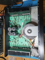
i know i am late to the party, but after reading through most of this thread i was so impressed by what Per started an achieved that i got the hifi bug again. i ordered a RC972 / RB981 on the bay.
While the seller told me they are working just fine i might disagree slightly.
In fact i was a bit disapointed firing everything up. Just like described by others it sounds "muddy" missing detail and punch.
even compared to an old Onkyo receiver.....
I was also quite surprised how much the amp vibrates with music playing. if you touch the case while playing a song i am fairly sure i can recognise the song even with speakers off 🙂
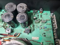
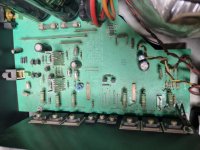
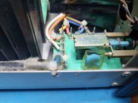
I opended it up and took a few pics to show the state it is in, and i am planning a few steps to get it up and running nicely again.
I will start with the Poweramp, and since its quite similar to smartdrivers 991 i will start with a few repairs and mods as described @ #393.
anything else i should replace?
i am looking forward to some tinkering, and brushing the dust of my scope.
however, i might need some advice on the way,
cheers!
Jürgen
i know i am late to the party, but after reading through most of this thread i was so impressed by what Per started an achieved that i got the hifi bug again. i ordered a RC972 / RB981 on the bay.
While the seller told me they are working just fine i might disagree slightly.
In fact i was a bit disapointed firing everything up. Just like described by others it sounds "muddy" missing detail and punch.
even compared to an old Onkyo receiver.....
I was also quite surprised how much the amp vibrates with music playing. if you touch the case while playing a song i am fairly sure i can recognise the song even with speakers off 🙂
I opended it up and took a few pics to show the state it is in, and i am planning a few steps to get it up and running nicely again.
I will start with the Poweramp, and since its quite similar to smartdrivers 991 i will start with a few repairs and mods as described @ #393.
- replacing caps would be the first thing, as a general question i wonder if you guys would replace all capacitors, or only electrolytics and foil.
- replace spark killer C001
- replace power supply caps
- i would like to replace C611/C612 with Wima MKS2 10u 50V, and compare the sound with electrolytics
- replace C623/C624 with Wima MKP4 100n
- replace VAS Resistors R623,R624,R629,R630 with 187R 1% 0.5W metal film
- replace trimmers with 2.2k Multiturn Types
- replace Transistors Q607–612 with matched 2SA1016KG-AA
anything else i should replace?
i am looking forward to some tinkering, and brushing the dust of my scope.
however, i might need some advice on the way,
cheers!
Jürgen
Attachments
Hi yurgs,
Honestly ... if it passes audio it is working fine in many people's minds. They were honest in that regard.
Do not replace every capacitor, you don't need to do that. Most coupling capacitors will be fine. They are sized so not signal voltage appears across them, so unless the originals are defective you will not have any performance increase. Polyester capacitors aren't very good either if you want to look at it that way, so you are exchanging imagined problems. Power supply and bypass may be rough. The main filters are often okay, check with your oscilloscope.
Do not use multi-turn pots! Leave the originals unless they are truly bad. Some fixed resistors will matter, most do not. Cheap metal film resistors are worse than the factory ones. Matching the diff pair very closely will matter.
Is the spark killer bad? If not, leave the poor thing alone. There are other things you can do that solve the issue I think you're trying to protect against.
-Chris
- Home
- Amplifiers
- Solid State
- Improve a Rotel amp THD by 20dB!