The driver transistors sit in a emitter follower configuration (ie. no amplification) and so it could be argued that they thus have less influence on audio quality than the previous stages. And indeed, in my experience you really have difficulties in hearing differences in A/B tests between good quality drivers.
But as 'audio quality' is inevitably subjective, the best advice is probably to simply try swapping sets of candidates - and have a good listen to each.
Per
PS.
The only reason that I can see that Rotel used the 600/631 as VAS transistors is because they set the VAS current to about 14mA, which with ~45V across gives over 0.6W heat generation in each. You could reduce the VAS current to say, 6mA by decreasing the values of R607-10 and R615-18.
Last edited:
Hi just a question no two actually
1) Do you have performed any THD+noise measurements after various mods ? i surfed the thread but found nothing
2) Have you used at any stage of the process some simulation SW ?
thank you very much
1) Do you have performed any THD+noise measurements after various mods ? i surfed the thread but found nothing
2) Have you used at any stage of the process some simulation SW ?
thank you very much
Hi it is me again I have found some graphs of THD+noise in the thread but about the ra971 model
Looking at the various service manuals it is possible to see how the topology has been maintaned somewhat similar at least for the integrated amps
There must be a reason
They have been very conservative considering that the first amp goes back to 50 years ago ?
I do not want to sound trivial but also noise should be addressed For instance i have seen from the lab report some power supply noise clearly passing through
I wonder what an upgrade of the power supply could bring to the table My feeling is that the capacitance in the power supply is too small
uFs re never enough ...
Almost always an increase of uF in the primary power supply caps quality and quantity brings the noise down in a measurable way
The evident peaks before the 1kHz test signal are clearly coming from the power supply and are not suppressed by the amp circuit (low PSRR?)
Imho is impressive what a very low noise amp can do to the musical experience
When the power is not very high i would even consider regulated voltage rails I know this is an added complexity but noise is a really bad beast
The less the noise the better
Could you please direct me to any post containing lab measurements ?
I'm a bit like Saint Thomas. I have to see to believe. And then when I've seen I become a fervent believer
I also propose to make a link in the original post to those pages for those skeptics
I am sure that showing the improvements will bring more people to this very excellent thread
Thank you sincerely and have a nice day
gino
Last edited:
Hi Gino,
It is all too easy to get concerned (read: panic) about things and start changing stuff - when the problem actually lies somewhere else.
I have more than once torn my hair out (and I don't have that much left) over some inexplicable measurement signal (or lack thereof) - only to find a broken test lead, wrong instrument setting or noisy nearby SMPS device to be the problem.
And I, of all people should really know better - my very first commercial project as a newly minted R&D engineer involved an expensive super low noise metal can opamp - which I couldn't get to do anything. Nada. Whatever I tried and checked. Oh no 😱- had I somehow stupidly already blown this $$$ opamp?
So this young engineer of course started doubting his entire education and was ready to hand back the diploma - when as a last resort I tried to pop in a discarded old uA741 that someone had left on the bench. And it worked!
I called the supplier who admitted that B&O had just returned a shipment of the expensive opamp. They had simply cut the can open and found that the manufacturer had 'forgotten' the chip-to-pin 6 bonding wire.😳
Good advice: Have a regular quality control (double) check of the equipment on the bench before starting a project.
(I probably should start to listen to that.)
Anyway, back to your questions.
1. Yes, I have tried to measure THD+N, my problem is that my Xonar7 measurement setup seems to be super sensitive to hum fields from any mains connection.
I think that I covered that in earlier posts on this thread, but I get 50Hz RTA peaks even when both the amp and the mains wall outlet switch are off. (!)
So neither the power supply or other circuits in the amp are causing this RTA signal.
Pull the plug out of the wall and it goes away, but there is of course not much music coming out of the amp.
You would think that my Fluke or Keithley DMM could measure this 50Hz ac RTA signal, but there is nothing. And definitely no audible hum.
So I have pragmatically decided to live with the RTA trace hum field artifacts for the time being.
Yes, to see is to believe - but you shouldn't believe all you see.😊
2. The late Bob Peace once said in one of his "What's All This ... Stuff, Anyhow?" article series:
There are lies, damned lies ... and Spice. Also: My favorite programming language is ... solder.
Ok, I think that Spice is a valuable tool for initial evaluation of circuit ideas and cabirio did quite some excellent Spice work on the 820AX circuit upgrades (see around pg.10).
Hope this waffling long reply answers your questions.
Best,
Per

Hi ! first of all sincere congratulations for your project and this thread. It is very educational for me that i am just a poorly skilled beginner
I have been impressed by your story It is quite surprising to realize that a manufacturer of such advanced device has skipped on QC
I had one and it seemed to work
https://www.ebay.it/itm/322543092641
Or you can do it with a little od DIY You just need a usb 2.0 type -b extension cord Open it in the middle and leave only the data wires connected and use the power wires with an external +5VDC low noise power supply Depending on the sound card consumption maybe even a battery could work providing a complete separation from the pc power supply noise
I am using a Behringer U-Phoria UMC202HD and it seems ok But i am focusing mostly line buffer and low voltages Up to 2-3Vrms the level that can bring a power amp to max power nothing more
Recently i have started some use of LTSpice and i am very fascinated Sometimes trying to change values i get results that look even ridiculous
But the blame is entirely on me of course
Your answers have been completely satisfactory and very kind.
Thank you very much again and kind regards,
gino
I have been impressed by your story It is quite surprising to realize that a manufacturer of such advanced device has skipped on QC
I see the issue You could try one of those Y usb cable that allows for the use of an external power supply instead of the pc power1. Yes, I have tried to measure THD+N, my problem is that my Xonar7 measurement setup seems to be super sensitive to hum fields from any mains connection.
I think that I covered that in earlier posts on this thread, but I get 50Hz RTA peaks even when both the amp and the mains wall outlet switch are off. (!)
So neither the power supply or other circuits in the amp are causing this RTA signal.
Pull the plug out of the wall and it goes away, but there is of course not much music coming out of the amp.
I had one and it seemed to work
https://www.ebay.it/itm/322543092641
Or you can do it with a little od DIY You just need a usb 2.0 type -b extension cord Open it in the middle and leave only the data wires connected and use the power wires with an external +5VDC low noise power supply Depending on the sound card consumption maybe even a battery could work providing a complete separation from the pc power supply noise
I am using a Behringer U-Phoria UMC202HD and it seems ok But i am focusing mostly line buffer and low voltages Up to 2-3Vrms the level that can bring a power amp to max power nothing more
yes but speaking of design the calculation step is not avoidable I have no skills in electronic design but i think that simulation SWs are very convenient2. The late Bob Peace once said in one of his "What's All This ... Stuff, Anyhow?" article series:
There are lies, damned lies ... and Spice. Also: My favorite programming language is ... solder.
Recently i have started some use of LTSpice and i am very fascinated Sometimes trying to change values i get results that look even ridiculous
But the blame is entirely on me of course
i agree absolutely and thank you for the suggestion I will look for those sims immediatelyOk, I think that Spice is a valuable tool for initial evaluation of circuit ideas and cabirio did quite some excellent Spice work on the 820AX circuit upgrades (see around pg.10).
Your answers have been completely satisfactory and very kind.
Thank you very much again and kind regards,
gino
I am quite sure that the 50Hz does not come through the usb. I put in an usb isolator, tried to run it from a laptop on battery power, etc.
And as I said, the hum peak disappears when I pull the mains plug from the wall.
It is most probably an electromagnetic field pickup from the amp mains side. As suggested by sgrossklass, the remedy could be to put an instrumentation or differential opamp before the Xonar7, making its input balanced.
Done right, eg. INA217 can give an extraordinary high CMRR that will effectively cancel any common mode signals on the inputs. I have actually made a protoboard for this, but haven't had the time to try it out yet. I will get round to it someday....
Chiao,
Per
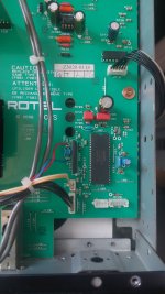
Hello and a good day, AngelP you have worked on many rotels, have you ever encountered something like this: Rotel RA06, after cleaning and re-assembly, the input selector will not work, amp will not boot with JP3A connector plugged in, if I unplug, amp boots normally but stays stuck in last input that was selected, plugging in the rotary selector after boot will not allow changing the input selection, it stays stuck on CD, I have replaced the Alps rotary switch with a known functional one, and upon testing the original switch it is fully functional, what am I missing here, why does it freeze the amp upon boot up? Removing JP3A connector with the amp already on but stuck, will make the amp boot normally (relays click and input will default to CD
I have checked the voltage to the Toshiba IC701, it's about 4.95V stable,
Thank you all for your time and help,
I have checked the voltage to the Toshiba IC701, it's about 4.95V stable,
Thank you all for your time and help,
Hi Christy,
That is a tough one to diagnose remotely.
It is normal for the amp's Toshiba uC to boot in last selected input mode with no selector switch attached (as it has not been told to do otherwise).
From your description it sounds like you may have some sort of damage or shorting on the selector pcb or its wires/contacts, maybe particularly around JP2A.
I would advise to re-clean and thoroughly inspect for possible solder balls, dirt/flux bridges - and such. And check all the diodes.
Then, with both the JP2B/3B disconnected I would measure the contacts between all connector pins to make sure that it works as it should - if you already haven't done that.
Lastly, you could try to reset the uC, but as it boots up nicely with no selector pcb, I actually don't think that will help.
Best,
Per
Thank you for the info, I checked all diodes on rhe selector pcb, all are good, I resoldered IC701, upon verifying with the remote control, the amp will not respond to any remote commands, standby/volume/input selection, none of the controls work, checked the remote with another rotel, it's working, is there any method of checking IC701? how can I reset it? I checked the datasheet but there is no reset pin? IC701 seems to be responsible for remote control also, or is it IC702? IC501 seems to be an an analogue multi-chanel switcher, but seeing it engages the CD, it should be good, what worries me is that it does not respond to any remote commands 🙁
Thanks again for any help and thoughts on this
Criss
Thanks again for any help and thoughts on this
Criss
Attachments
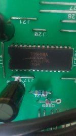
Pin 33 on the TMP74C400BN is the reset (active low) pin.
Turn the amp off, short C703 with a test wire or something, turn the amp on and then remove the short.
The uC will then be reset.
If you do find evidence that the uC is defective, I am afraid the bad news is that you are totally out of luck.
It is an OTP (pre-programmed) device and Rotel claims that they do not have spares (or the source code) anymore.
But, as I said, I doubt that IC701 is the problem - unless you have used a non-earthed iron and not at least touched the chassis with the tip before soldering.
If the problem arose after cleaning, switches and contacts are the first usual suspects.
Per
it worked, thanks a lot AngelP powering on the amp and shorting c703 did it, it seems the uC got stuck, no ideea how, interesting thing
Thank you, could not have done it without your help, thank you again 🙂
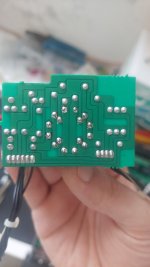
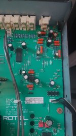
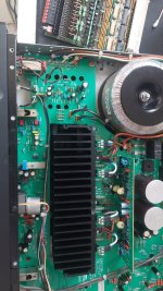
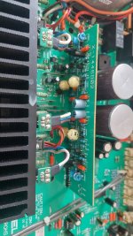
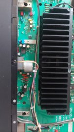
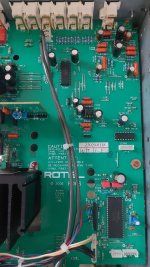
Here are some photos and mods I did to this RA-06, inspired by the ones posted here
Upped feedback caps to 220uf from 100uf
Removed C601/C602, inatalled jumper wire
Replaced VAS transistors with C2911/A1209
Replaced pre-drivers with C2910/1208
Recapped with Panasonic FM, all caps and low voltage psu, upped caps to to 1800uf and 220uf from 1000uf and 100uf,
Tone caps,Replaced with Wima FKP2 and FKC2
Replaced main opamps with AD712, analog monitor and phono replaced with original Signetics 5532
All ceramic caps replaced with MLCC from Murata
Bias and some low value electrolitics also replaced with Wima MKP4 and MLCC
Amp sounds so much better, still net to lower VAS current a little, maybe change from 100R to 220R cause poor VAS transistors are hot as hell, and maybe the blue leds to red or orange 😅
PS: for anyone working on these amps, if you power on the amp without the input selector switch the uC will get stuck, and you will need to reset it, preferably do not power on without selector switch
This should apply to RA985BX/RA-02/RA-06
Criss
Attachments

Last edited:
Rotel RA-820BX3
A chap called Paul in London contacted me out of the blue to say that he has been following this thread for years and really enjoyed it.
He apparently appreciated it so much that he decided that I should have his surplus RA-820BX3 for free. Thanks, Paul! Most generous.🙏
I reciprocated by saying that I would have a ‘look into this gift amp’s mouth’ and maybe report any upgrade on this thread.
So Paul, your amp is now the new ‘star’🌟 on this diyAudio thread!

Turned the amp on and it worked, actually sounded quite nice. And it looks nice on the outside, too. Inside, perhaps less so, more on that later.
The 820BX3 is an is an inverting amp (a positive going input gives a negative output) – I won’t go into the old discussion whether this better reflects what the recording microphones register or what air flow happens in a vented box or a backloaded horn, etc.
In any case, it is a different topology from what I have previously covered in this thread. It differs a lot from Stan Curtis’ other Rotel designs – actually to a degree where I almost wonder whether it actually was his work.
Strangely, the THD spec is listed as a modest 0.3% - 10 times higher than other Rotels of about roughly the same era, e.g. RA-931.
I see no reason why an inverting amp per se should give such a difference in performance.
(In fact when I design with opamps, I sometimes prefer to use the inverting configuration due to the simpler feedback and predictability).
A brief look under the amp’s top cover and comparing with the tech manual shows that there must have been two designs or versions with the exact same model name, the manual definitely differs from the amp I had open on the bench.
There is a difference in the placement of components, in particular the reservoir caps.
And of course there are the usual Rotel drawing mistakes in the schematic, all in all a bit chaotic, but ‘tant pis’ as they say…. nothing that can’t be corrected or plainly ignored.
Diving in a bit deeper, however, should raise quite a few eyebrows.
Stay tuned…
A chap called Paul in London contacted me out of the blue to say that he has been following this thread for years and really enjoyed it.
He apparently appreciated it so much that he decided that I should have his surplus RA-820BX3 for free. Thanks, Paul! Most generous.🙏
I reciprocated by saying that I would have a ‘look into this gift amp’s mouth’ and maybe report any upgrade on this thread.
So Paul, your amp is now the new ‘star’🌟 on this diyAudio thread!
Turned the amp on and it worked, actually sounded quite nice. And it looks nice on the outside, too. Inside, perhaps less so, more on that later.
The 820BX3 is an is an inverting amp (a positive going input gives a negative output) – I won’t go into the old discussion whether this better reflects what the recording microphones register or what air flow happens in a vented box or a backloaded horn, etc.
In any case, it is a different topology from what I have previously covered in this thread. It differs a lot from Stan Curtis’ other Rotel designs – actually to a degree where I almost wonder whether it actually was his work.
Strangely, the THD spec is listed as a modest 0.3% - 10 times higher than other Rotels of about roughly the same era, e.g. RA-931.
I see no reason why an inverting amp per se should give such a difference in performance.
(In fact when I design with opamps, I sometimes prefer to use the inverting configuration due to the simpler feedback and predictability).
A brief look under the amp’s top cover and comparing with the tech manual shows that there must have been two designs or versions with the exact same model name, the manual definitely differs from the amp I had open on the bench.
There is a difference in the placement of components, in particular the reservoir caps.
And of course there are the usual Rotel drawing mistakes in the schematic, all in all a bit chaotic, but ‘tant pis’ as they say…. nothing that can’t be corrected or plainly ignored.
Diving in a bit deeper, however, should raise quite a few eyebrows.
Stay tuned…
Any chance of getting some measurement results?Turned the amp on and it worked, actually sounded quite nice.
Rotel RA-820BX3 Schematic:
Firstly, note the numerous compensation cap circuits (circled). You could be excused for guessing that the design engineers had a fair bit of amp instabilities to struggle with? And patch up?

Note that the B1 and -B1 rails says ±41V – whereas in this amp they are actually ±31V even though the transformer designation is the same, T-1017GF ??
But mainly note the huge difference in the R607/609 LTP emitter resistors? This would cause both non-linearity, distortion and a big DC output offset – hence the need for an offset trimmer?
What goes on in this amp?
If we re-draw to simplify the amp design to show the feedback and input loading we get:

I covered the ‘T’ feedback circuit in post #910 on pg.46 It is a clever way of getting high gain without having to use high value resistors (although Johnson would say that a 120k is plenty noisy).
But the +input loading definitely looks strange to me. In BJT amps, it is desirable if not essential to load the + and – inputs with equal resistances. Here, that is (sort of) true at higher frequencies where the 0.1uF shorts out the 270k.
But at DC, there is a more than 13 times difference in the input loading!! DC offset guaranteed!
You would only do such a design if you actually wanted that! In an audio amp??
And someone please explain the reasons for (or advantages of) the 100nF C621 and also the 1nF parallel C609 at the input.
This confused engineer would regard it as a deliberate, unwanted ripple and noise coupling into the LTP circuit. But I may be wrong – that would definitely not be the first time.😊
Next, on to a closer look at the board and making some measurements.
Stay tuned…..
Firstly, note the numerous compensation cap circuits (circled). You could be excused for guessing that the design engineers had a fair bit of amp instabilities to struggle with? And patch up?
Note that the B1 and -B1 rails says ±41V – whereas in this amp they are actually ±31V even though the transformer designation is the same, T-1017GF ??
But mainly note the huge difference in the R607/609 LTP emitter resistors? This would cause both non-linearity, distortion and a big DC output offset – hence the need for an offset trimmer?
What goes on in this amp?
If we re-draw to simplify the amp design to show the feedback and input loading we get:
I covered the ‘T’ feedback circuit in post #910 on pg.46 It is a clever way of getting high gain without having to use high value resistors (although Johnson would say that a 120k is plenty noisy).
But the +input loading definitely looks strange to me. In BJT amps, it is desirable if not essential to load the + and – inputs with equal resistances. Here, that is (sort of) true at higher frequencies where the 0.1uF shorts out the 270k.
But at DC, there is a more than 13 times difference in the input loading!! DC offset guaranteed!
You would only do such a design if you actually wanted that! In an audio amp??
And someone please explain the reasons for (or advantages of) the 100nF C621 and also the 1nF parallel C609 at the input.
This confused engineer would regard it as a deliberate, unwanted ripple and noise coupling into the LTP circuit. But I may be wrong – that would definitely not be the first time.😊
Next, on to a closer look at the board and making some measurements.
Stay tuned…..
Rotel RA-820BX3 Board:
After the usual old Rotel de-dusting ritual, is became clear that there are some serious blackening of the pcb around the VAS transistors.
A quick temperature measurement of the Q617/619 pair shows over 90ºC!! And of course I managed to burn a fingertip on these bolted together TO-126 transistors. Also note the beginning of blackening of the big 910R 2W resistors. All in the same limited pcb area.

So I decided to calculate the set currents through each stage of the amp.

Going from right to left:
The recommended output bias setting is 2.5mV over the 0.22 ohm – giving only 11 mA in the transistors on the large heatsink.
Whereas the drivers and their 2W 910R resistors run at 35mA, three times as much?
The VAS stage trannies runs as 23mA (!) with no heat sink. No wonder that they get so hot.
And finally, the first LTP collectors get only 164 uA, or 82 uA each.
Not your traditional set of currents.
After the usual old Rotel de-dusting ritual, is became clear that there are some serious blackening of the pcb around the VAS transistors.
A quick temperature measurement of the Q617/619 pair shows over 90ºC!! And of course I managed to burn a fingertip on these
bolted together TO-126 transistors. Also note the beginning of blackening of the big 910R 2W resistors. All in the same limited pcb area.So I decided to calculate the set currents through each stage of the amp.
Going from right to left:
The recommended output bias setting is 2.5mV over the 0.22 ohm – giving only 11 mA in the transistors on the large heatsink.
Whereas the drivers and their 2W 910R resistors run at 35mA, three times as much?
The VAS stage trannies runs as 23mA (!) with no heat sink. No wonder that they get so hot.
And finally, the first LTP collectors get only 164 uA, or 82 uA each.
Not your traditional set of currents.
Rotel RA-820BX3 Repairs and measurements:
Firstly, the secondary +18V supply voltage to the phono preamp stage was out, just turned out that one of the regulator transistors was bad, replacing it solved the problem.
Then I measured the output DC and managed to trim it to 0mV – well, at least temporarily.
It drifted slowly up and down – sometimes as much as 700mV(!), depending on whether I was looking down into the amp or not. Clearly an unwanted high temperature sensitivity or fault somewhere and something that needs to be looked into.
So to find the guilty circuit(s), I got me trusted old freeze spray out. A spray on the TO-3Ps on the heatsinks did not change things much, as expected.
Spraying the hot VAS did give a brief negative DC, as did spraying the second LTP stage.
But a short spray on the first PNP pair immediately 🚀shot the output to the positive rail! From where it slowly drifted back.
Aha, so perhaps one of the LTP trannies was beyond its use-by date? I replaced with a matched pair of KSA992s and tried again - a bit better, but still got a massive offset on freezing.
(The original SA1016s were ok, but not - or perhaps no longer - closely matched, they had a 13% difference in hFE).
So I ran a first RTA on the amp. THD was 0.11% with a dominant 3rd harmonic.

(In case some eagle-eyed readers should notice, I had to use a laptop setup with another version of REW, so the trace looks a bit different to what I am used to, particularly at low frequencies. But it will have to do for now).
Now what?
After this long diyAudio thread has now passed 1000 posts, I suddenly find myself going full circle and right back to Post #1:
Yes, it is ‘Déjà vu’ all over again - sort of like the ‘Groundhog Day’ movie (although in this case it is almost ‘Groundhog Decade’ )😉
The thread's longevity is totally down to all of you readers and contributors - and I thank you all for the years of good Rotel upgrading fun.
I guess that the question now is: Do we really want to go through it all again? And do I want to go again?
..............Of course I do! 😍👍
Firstly, the secondary +18V supply voltage to the phono preamp stage was out, just turned out that one of the regulator transistors was bad, replacing it solved the problem.
Then I measured the output DC and managed to trim it to 0mV – well, at least temporarily.
It drifted slowly up and down – sometimes as much as 700mV(!), depending on whether I was looking down into the amp or not. Clearly an unwanted high temperature sensitivity or fault somewhere and something that needs to be looked into.
So to find the guilty circuit(s), I got me trusted old freeze spray out. A spray on the TO-3Ps on the heatsinks did not change things much, as expected.
Spraying the hot VAS did give a brief negative DC, as did spraying the second LTP stage.
But a short spray on the first PNP pair immediately 🚀shot the output to the positive rail! From where it slowly drifted back.
Aha, so perhaps one of the LTP trannies was beyond its use-by date? I replaced with a matched pair of KSA992s and tried again - a bit better, but still got a massive offset on freezing.
(The original SA1016s were ok, but not - or perhaps no longer - closely matched, they had a 13% difference in hFE).
So I ran a first RTA on the amp. THD was 0.11% with a dominant 3rd harmonic.
(In case some eagle-eyed readers should notice, I had to use a laptop setup with another version of REW, so the trace looks a bit different to what I am used to, particularly at low frequencies. But it will have to do for now).
Now what?
After this long diyAudio thread has now passed 1000 posts, I suddenly find myself going full circle and right back to Post #1:
Can this Rotel amp be improved by a 20dB reduction in THD ???
Yes, it is ‘Déjà vu’ all over again - sort of like the ‘Groundhog Day’ movie (although in this case it is almost ‘Groundhog Decade’ )😉
The thread's longevity is totally down to all of you readers and contributors - and I thank you all for the years of good Rotel upgrading fun.
I guess that the question now is: Do we really want to go through it all again? And do I want to go again?
..............Of course I do! 😍👍
Last edited:
- Home
- Amplifiers
- Solid State
- Improve a Rotel amp THD by 20dB!