Hi Paulus,
I honestly don't know, I have seen it done a number of different ways I guess that it depends on the components and layout.
Eg. the RA-300 uses a single 0.01u cap across the secondary as you suggest, whereas the later RA-8/900 series all use four caps at the rectifier. All rated 500V.
Whatever you decide, before you start soldering around this area please ensure that the mains plug is out of the wall and that the reservoir caps have been fully discharged.
You have about 150V and umpteen milli-Farads here, so one tiny slip of the soldering iron could provide a nasty early new year's firework display.
You will probably notice that the soldering tip has gone - evaporated
Which is also why I always have a couple of spare Weller tips in the drawer.....😱
Cheers,
Per
Rotel overheating problems
Hi Paulus and Tony,
I have started to upgrade a RA-971 to see if I can make the current mirror and VAS modules work in this double differential amp topology and whether something similar could be applied to your RB-980/991 amps.
And have decided to post here as it may also be of interest to other Rotel owners or readers on this thread.
But first some thoughts on the overheating problems in these Rotels, particularly in and around the VAS and driver heatsinks.
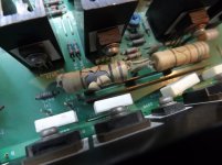
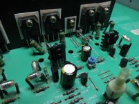
Rotel used to apply heavy emitter dropping resistors for the driver stage of this amp topology, but this started giving problems with the higher and higher rail voltages in RA-940/960 and later. These 3W 1k power resistors sit from each driver emitter to the opposite rail, whereby they dissipate several watts and get very hot – I have measured way over 125 oC and that eventually takes a toll on them, see enclosed picture.
They also cook everything around them, one could call it local global warming?
As I remember the idea behind these drop resistors is to ensure enough available current drain to ensure a quick cut-off the of the power transistor bases in order to reduce HF crossover distortion - maybe someone here in the know could explain things better/further?
Anyway, in the RA-980 and I believe in most later amps Rotel found that this feature could instead be resolved by replacing them with a simple 47R between the driver emitters, whereby the driver transistors now take the heat.
The 47R only has two Vbe voltage drops across it, so the current through it is 1.2V / 47R = 26mA.
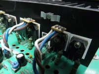
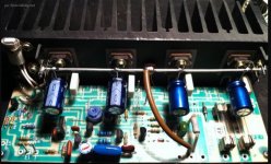
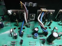
But with 49V rails and 26mA through, the driver transistors now require separate heatsinks and even so they still get very hot. The RA-971 that sits on my workbench has clearly had such problems and apparently very late in the development Rotel had actually decided to remove the heatsinks and move the drivers to the top of the output transistors, see pic.
I don’t know what these poor power trannies had ever done to deserve this, and yet the driver temperatures are still >70 oC due to the resulting ineffective heatsinking – and it doesn't look very elegant, does it?
Ok, let's see what can be done........
Per
Hi Paulus and Tony,
I have started to upgrade a RA-971 to see if I can make the current mirror and VAS modules work in this double differential amp topology and whether something similar could be applied to your RB-980/991 amps.
And have decided to post here as it may also be of interest to other Rotel owners or readers on this thread.
But first some thoughts on the overheating problems in these Rotels, particularly in and around the VAS and driver heatsinks.
Rotel used to apply heavy emitter dropping resistors for the driver stage of this amp topology, but this started giving problems with the higher and higher rail voltages in RA-940/960 and later. These 3W 1k power resistors sit from each driver emitter to the opposite rail, whereby they dissipate several watts and get very hot – I have measured way over 125 oC and that eventually takes a toll on them, see enclosed picture.
They also cook everything around them, one could call it local global warming?
As I remember the idea behind these drop resistors is to ensure enough available current drain to ensure a quick cut-off the of the power transistor bases in order to reduce HF crossover distortion - maybe someone here in the know could explain things better/further?
Anyway, in the RA-980 and I believe in most later amps Rotel found that this feature could instead be resolved by replacing them with a simple 47R between the driver emitters, whereby the driver transistors now take the heat.
The 47R only has two Vbe voltage drops across it, so the current through it is 1.2V / 47R = 26mA.
But with 49V rails and 26mA through, the driver transistors now require separate heatsinks and even so they still get very hot. The RA-971 that sits on my workbench has clearly had such problems and apparently very late in the development Rotel had actually decided to remove the heatsinks and move the drivers to the top of the output transistors, see pic.
I don’t know what these poor power trannies had ever done to deserve this, and yet the driver temperatures are still >70 oC due to the resulting ineffective heatsinking – and it doesn't look very elegant, does it?
Ok, let's see what can be done........
Per
Attachments

These are basically single-ended driver stages rather than the more common push-pull. If you have the current / power dissipation to spare, great. But as always, even in Class A you can expect twice the idle current for the same driving capabilities.As I remember the idea behind these drop resistors is to ensure enough available current drain to ensure a quick cut-off the of the power transistor bases in order to reduce HF crossover distortion - maybe someone here in the know could explain things better/further?
That's the classic push-pull driver arrangement.Anyway, in the RA-980 and I believe in most later amps Rotel found that this feature could instead be resolved by replacing them with a simple 47R between the driver emitters, whereby the driver transistors now take the heat.
Which, btw, is quite healthy and should minimize any shoot-through issues at high frequencies.The 47R only has two Vbe voltage drops across it, so the current through it is 1.2V / 47R = 26mA.
Well, you can't actually see it very well. Are they like literally sandwiched on top?But with 49V rails and 26mA through, the driver transistors now require separate heatsinks and even so they still get very hot. The RA-971 that sits on my workbench has clearly had such problems and apparently very late in the development Rotel had actually decided to remove the heatsinks and move the drivers to the top of the output transistors, see pic.
Moving them to the main heatsink per se is good news for thermal stability. They'd just need some better thermal transfer.
BTW, are these silpads behind the transistors? While convenient, the last word in thermal transfer they are not...
Well, you can't actually see it very well. Are they like literally sandwiched on top?
Moving them to the main heatsink per se is good news for thermal stability. They'd just need some better thermal transfer.
BTW, are these silpads behind the transistors? While convenient, the last word in thermal transfer they are not...
Hi sgross,
I couldn't agree more.
Yes, the drivers are just placed on top of the power trannies using the same screw.
I guess that in the current position the main heat sink path for the drivers are out through the oversized 20AWG leads.
There are actually already two drilled and M3 tapped holes in the heatsink above the power trannies, so my first plan was to move the drivers and use a simple double clip (see pic) to clamp them directly to the heatsink.
The 2SC3902/A1507 are types that have plastic coating all over, so while it would still be a bit fiddly I reckoned that it was doable.
But then I decided to try reducing the current and see what effects this may have. I am working on this right now and will take your HF shoot-through point into account.
Per
Attachments
Rotel overheating problems
Ok, I searched the web and found very little concrete info on this issue.
I still wondered: ”It is really necessary to whack so much current (and excessive heat) through the driver stage to ensure this power transistor base cut-off?”
What if I reduced it by 50% - or more? It is simple to do by just increasing the 47R to >100R.
If this resistor value increase slows the cutoff effect too much, then maybe add a small speed-up capacitor across it?
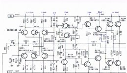
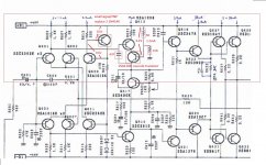
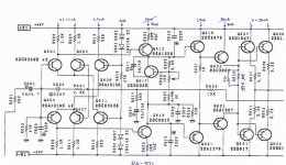
In the end, mainly based on intuition, I decided on 157R || 100nF to replace the 47R, see enclosed schematic.
Instead of tinkering with a Spice model I decided it was just as fast to actually try it out, measure stability, temperatures and THD before and after and have a good listen to the amp.
Results:
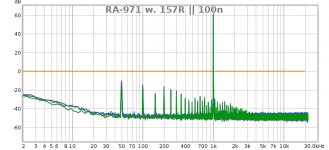
Stability is just as excellent as before and THD remained completely unchanged at 0.0013%, see the enclosed RTA traces, blue is before, green after and the red is the fractional difference between them.
In the listening test, there was simply no audible difference.
But the driver transistor temperatures dropped from 70°C to 42°C
As sgrossklass pointed out, there is a possible HF problem if the output transistors don’t cut off quickly enough.
Then graduately both the NPN and PNP could briefly be conducting at the same time, eventually causing a heavy increase in the output stage current which is not good for business.
To test this issue I decided to monitor the output bias voltage over the 0.22R while feeding the amp with 20Khz and increasing it up to the amp’s upper -3dB bandwidth.
The bias did indeed increase from the 8mV setting below 30kHz to about 11.5mV at 330kHz.
That could be due to a number of things, but the most important finding was that there was absolutely no measurable difference between the upgraded right channel and the original left.
I tried with both sine and square wave input signals and different multimeters, my trusted Fluke and a much slower cheap DVM. No difference.
Well, I would consider that job done - unless of course someone can point to other potential problems by doing this?
Per
Ok, I searched the web and found very little concrete info on this issue.
I still wondered: ”It is really necessary to whack so much current (and excessive heat) through the driver stage to ensure this power transistor base cut-off?”
What if I reduced it by 50% - or more? It is simple to do by just increasing the 47R to >100R.
If this resistor value increase slows the cutoff effect too much, then maybe add a small speed-up capacitor across it?
In the end, mainly based on intuition, I decided on 157R || 100nF to replace the 47R, see enclosed schematic.
Instead of tinkering with a Spice model I decided it was just as fast to actually try it out, measure stability, temperatures and THD before and after and have a good listen to the amp.
Results:
Stability is just as excellent as before and THD remained completely unchanged at 0.0013%, see the enclosed RTA traces, blue is before, green after and the red is the fractional difference between them.
In the listening test, there was simply no audible difference.
But the driver transistor temperatures dropped from 70°C to 42°C
As sgrossklass pointed out, there is a possible HF problem if the output transistors don’t cut off quickly enough.
Then graduately both the NPN and PNP could briefly be conducting at the same time, eventually causing a heavy increase in the output stage current which is not good for business.
To test this issue I decided to monitor the output bias voltage over the 0.22R while feeding the amp with 20Khz and increasing it up to the amp’s upper -3dB bandwidth.
The bias did indeed increase from the 8mV setting below 30kHz to about 11.5mV at 330kHz.
That could be due to a number of things, but the most important finding was that there was absolutely no measurable difference between the upgraded right channel and the original left.
I tried with both sine and square wave input signals and different multimeters, my trusted Fluke and a much slower cheap DVM. No difference.
Well, I would consider that job done - unless of course someone can point to other potential problems by doing this?
Per
Attachments
To improve a Rotel amp, I would like to make below mod.
1. Using small signal transistor to replace 1N4148 diodes for a stable current supply
2. For the VAS stage, add one more cascode transistor to improve linearity and reduce THD
I just point out half mod circuit for the positive supply rail, so you have to mod the negative supply rail the same way
1. Using small signal transistor to replace 1N4148 diodes for a stable current supply
2. For the VAS stage, add one more cascode transistor to improve linearity and reduce THD
I just point out half mod circuit for the positive supply rail, so you have to mod the negative supply rail the same way
Attachments
Output power transistors local supply cap mod - this is not a new idea but it's very useful for most integrated amp.
For most of the integrated amp, due to the amp case spacing limit and costing matter, an amp usually built with not so high current output transformer, single supply voltage with just enough smoothing capacitors for both channels and some supply voltage PCB layout with a long distance and narrow copper routes to output power transistors, this make an amp in a normal listening volume level sounding ok.
But when we need more output form the amp, due to the above amp built quality, for the instant peak output moment the output power transistor cannot get sufficient output current form the power supply so that the the sounding is not so good, like a narrow stage image, soft bass and harsh.
This output power transistors local supply cap little mod built a small reservoir to supply enough current for instant peak output, it improve an integrated amp to perform in a higher level.
The mod just add a cap of 330uF~470uF to each output power transistors, with one cap leg direct solder to the collectors or emitters (depend on your amp is a common collectors or emitters to the supply rails) of each output power transistor and other cap legs joint together and connect to the supply ground of the amp board.
Attachments
Last edited:
To improve a Rotel amp, I would like to make below mod.
1. Using small signal transistor to replace 1N4148 diodes for a stable current supply
2. For the VAS stage, add one more cascode transistor to improve linearity and reduce THD
I just point out half mod circuit for the positive supply rail, so you have to mod the negative supply rail the same way
Hi Patrick,
Yes, that would probably work. I used to dabble with cascodes (see post #25), but in the end stopped due to the pure practicality of placing the extra components in an elegant way.
A lot depends on the actual pcb layout - and even then it is still fiddly work.
Also, while the VAS cascode will reduce distortion it does not reduce the load on the input LTPs. Which is where I was hoping to go once I get around to modding the RA-971 VAS stage, hopefully by the end of the week.
Regarding the distributed extra capacitors at the output trannies, I would have thought that given the order any decent power transistor would suck a 330u dry in an instant?
BTW, have you done any measurements?
Cheers,
Per
I was hoping to modding the RA-971 VAS stage
It's true that mod in an elegant way can't make so much changes in mod.
Regarding the distributed extra capacitors at the output trannies, I would have thought that given the order any decent power transistor would suck a 330u dry in an instant?
BTW, have you done any measurements?
No measurements on this, when compare to the original supply cap capacity, not sure how to measure an extra small cap in the circuit
This mod idea was introduced by someone in the past, maybe the mod is not in an elegant way so that no one to do that Today.
People doing this mod has positive comment, so that maybe some diehard diyer will be interested.
I know integrated amp got weak point to handle some music, so that people buying expensive pre amp and power amp.
An integrated amp's original supply cap capacity can handle most of the music playing, but when a peak music signal of a short time(maybe millisecond,microsecond) present, I think that little cap can help a little and make the different in sounding.
just sharing only, thanks
🙂
Hi Patrick,
You could try putting a scope on the power transistor rail pin, feed the amp with short pulses (or a square wave) and measure the voltage dips with and without the caps.
BTW, you did a very nice job on the schematic changes. What program did you use?
Per
You could try putting a scope on the power transistor rail pin, feed the amp with short pulses (or a square wave) and measure the voltage dips with and without the caps.
BTW, you did a very nice job on the schematic changes. What program did you use?
Per
Hi Patrick,
You could try putting a scope on the power transistor rail pin, feed the amp with short pulses (or a square wave) and measure the voltage dips with and without the caps.
BTW, you did a very nice job on the schematic changes. What program did you use?
Per
Thanks,
I have an analog scope, an audio freq. signal generator and a 20 watt 8 ohm metal resistor load for testing, I think these equipment can't do the measurement.
I just use the Win 7 built-in paint tool to make the schematic changes(simple cut, paste and edit) 😀
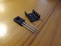
Right, that seems to be the driver stage overheating sorted. I removed the unsightly heavy wire setup and placed the driver transistors back on the pcb. Here, they ran a bit warm so I ordered a set of TO-126 heat sinks off ebay. They turned out to be quite a bit smaller than I thought, see pic. But, they actually did the job and the driver heatsink temp is now about 44°C – I can live with that 😎 And things looks so much more tidy.
Out of curiosity I also tried the extra clip on the main heatsink and it works. That 70°C driver went down to 46°C. But placing two transistors under the same clip proved difficult – sort of like herding cats
So, it's on to the hot VAS stage then....
Out of curiosity I also tried the extra clip on the main heatsink and it works. That 70°C driver went down to 46°C. But placing two transistors under the same clip proved difficult – sort of like herding cats
So, it's on to the hot VAS stage then....
Attachments
The bias setting and stability is now much better in the modded R channel.The original hot bias tended to drift slowly +/- 1mV around the 8mV setting, indicating thermal feedback issues.
Sort of like a PID servo regulator where the "P" or "D" are too much for the stability or the time constants in the loop.
There is still a small drift which I hope to stabilise in the VAS stage mod.
Meanwhile I will try to replace the white Rotel silpad (which is a mica slab with alumina film on both sides) for the bias tranny with a Bergquist pad which is supposed to have a lower thermal resistance and thus faster thermal feedback.
RA-971 overheating problems - VAS stage
Firstly, the Ra-971 TO-92l VAS transistors Q613-616 were boiling away at 72°C, starting to discolour the pcb.
And the output bias current still drifts slowly around the 8mV (36mA) setting. Clearly, there are still some thermal issues.
I looked again at the schematic and wondered why Rotel decided to whack 14mA through this VAS stage.
OK, normally, some VAS current (6-8mA) is needed to feed the following power stage loading – but here, the VAS transistors only feed into an extra emitter follower stage running at just over 2mA collector current?
Such a high VAS current not only causes overheating, but also increases unwanted stuff like the Early effect, non-linearities and increases distortion.
And I was hoping to use the compact VAS modules I designed for the RA-931 on these high rail voltage amps.
But in particular for Paulus’ RB-991 with its 73Vdc rails, the heat dissipation in each module would be way over 0.5W which would definitely fry the small max 300mW SOT-23 trannies on the modules.
So I decided to go for broke and - as a first step try reducing the existing 14mA VAS stage current all the way down to 4mA - to see what happens.
This is easily done by increasing the VAS emitter resistors R621/622 from 100R to 365R.
Well, nothing happened.
Except that the Q618 bias setting circuit now couldn't provide more than max 4.5mV (20mA) output stage current.
Easily sorted by changing the R938 1k5 resistor to 1k.
Bias setting now also easier and more stable.🙂
And the VAS trannies’ temp dropped drastically down to 38°C. I swear I could see a thankful smile on their old weathered TO-92l faces.
RTA measurements showed a small drop from 0.0018 to 0.0012%, listening test (on headphones) - no audible L to R changes.
I will also check the slew rate limitation onset, but I don't expect any serious changes.
So - after 5 cheap passive component changes - the overheating issues are gone. I'm actually pretty chuffed with that.😀
Attachments
Hi there Per,
I really would like to see Stan Curtis's face when he sees what you're doing with his designs but most of all when he hears what these modifications do with the sound.
For me, with 2 partly modified RB-991 amplifiers, the changes made by Per bring so much more finesses, detail and clarity to the sound that they are in another league. I really do not know how to express myself otherwise.
Keep it up Per
If there are changes to be made you know where to find me 😀
Cheers, Paulus
Hi there Per,
I really would like to see Stan Curtis's face when he sees what you're doing with his designs but most of all when he hears what these modifications do with the sound.
Steady on Paulus, now how does the old saying go ..... "If I can see further, it is because I stand on the shoulders of giants".
Giants like Curtis, Baxandall, Linsley-Hood, Pass, Self, Otala - the list goes on.
And definitely also the shoulders of my professors at DTU (Technical Uni of Denmark), who with a stoic patience managed to haul me through all the math, acoustics and electronics.
Particularly my electro-acoustics teacher Prof. Staffeldt who introduced me into the IEEE Audio Society back in the hay days of discrete audio development - and of DIY.
Cheers,
Per
Credit where credits due Per
Where i'm standing, you taught me but you were taught by your professor at the uni.
It is all in the eye of the beholder, you are a very nice and humble person Per and i respect that.
Cheers, Paulus
Where i'm standing, you taught me but you were taught by your professor at the uni.
It is all in the eye of the beholder, you are a very nice and humble person Per and i respect that.
Cheers, Paulus
I have recently had a question like ”I don’t get it - what has this PID stuff now suddenly anything to do with the bias in amplifiers?” Maybe a more basic explanation is required – and I don’t know if this is the right forum for it – but, after all if more information gives more people further understanding and interest to dabble with audio electronics that would definitely be worth a few lines on this blog? So, even though I have never had much teaching experience, I’ll give it a go.
Bipolar Junction Transistors (BJT) are fantastic components with amazing properties, but they do have one serious drawback – they are sensitive to temperature in a way that can make them seriously – even fatally overheat.
The current amplification factor ”beta” or hFE (which is the factor that multiplied with the transistor input base current gives the output collector current: IC = hFE * IB) of a BJT increases with temperature (whereas the equivalent gm of a FET does not). This means that if a BJT is left uncontrolled to warm up, its IC current will increase – and cause further warming, more heat and so on – until this thermal runaway finally ends in smoke and tears.
One common example is the output power transistors on the heatsink. We must establish some negative thermal feedback correction to avoid this runaway happening. Which is why power stages have their output bias setting transistors bolted on the heatsink next to the output transistors.
This bias transistor (and circuitry) actually acts as an adjustable ”resistor”, see pic. Its purpose is to raise the base DC voltages of the output transistors (just) up into their ”ON” active linear range to avoid crossover distortion, and it does so by changing its ”resistance” to the VAS stage current that runs through it. Referring tho the pic, if you turn the trimmer wiper to the top, the transistor turns fully ON and the circuit acts as a very low ”resistor” - effectively grounding the output transistors. Conversely, if you turn the trimmer all the way down, the transistor turns OFF and is a very high ”resistance”. Somewhere in between is the sweet spot where you can finely adjust the output bias current. Quite clever, actually.
Now, this bias transistor is also a BJT which will increase its hFE with temperature. So, as it is heated by the increasing heatsink temperature, this increases its IC and thus lowers the bias circuit’s apparent ”resistance”. Which in turn gradually reduces the output transistors base voltages and thereby their ”ON” states and output bias current back to safe levels, avoiding thermal runaway.
You can see this effect if you monitor the bias voltage setting pins (ie. the voltage over one of the 0.22 ohm emitter resistors) when turning on a cold amplifier. On some (not all) amps the bias current will overshoot the setting and slowly sink back to the desired level as thermal equilibrium is attained. (Which is also why you should wait 10-15 minutes to let the amp warm up before attempting to set the bias).
It is a slow, sort of a ZEN like monitoring exercise and you are actually encouraged to clasp your hands and go ”ummmmmm” while watching it. Maybe throw in a small prayer that the amp will not self-combust in front of your very eyes. That normally works for me.
As for this PID control stuff? Well, it is basically a PID thermal feedback control loop, definitely not perfectly tuned, but most often - it does the job.
I hope this basic explanation makes any sense. Otherwise, I intend to follow the advice of the great Tom Lehrer: ”If people can’t communicate – the very least they can do is to SHUT UP!”
Attachments

Last edited:
I'm reading it all, several times actually...
Just wish you would finish up on that thing and move along to the Adcom GFA-5200, 5300, 5400 series all-mosfet amps!
Just wish you would finish up on that thing and move along to the Adcom GFA-5200, 5300, 5400 series all-mosfet amps!
- Home
- Amplifiers
- Solid State
- Improve a Rotel amp THD by 20dB!