I've spent the weekend splitting the DAC from the FIFO with a view to fitting into a 2U case.
I wired it up for i2S as per this image plus the MCLK coax.
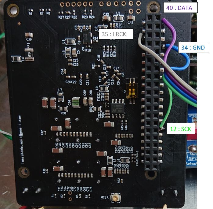
This did not work, but using a 40 pin ribbon cable did. There must be more connections required than just DATA, SCK, LRCK + GND. ??
I'm using an Allo USBridge Sig rather than a Pi though I suspect this makes no difference.
May be its need to connect the control interface SDA/SCL too, in the FifoPi Manual they also remarked in the 40pin Table at Pin 3&4.
Hi Umarkus,
I start with those as well...diyinhk...moving to salas ultrabib 1.3 was eyeopening...big difference...at least for the dac. The battery stuff from ian is simply there as i wanted to try...i have not yet an opion on that, but it is good, but not like i would say it is theholy grail. diyinhk vs. salas is a clear game.
btw. UltraBIB and Refelktor-D on its way 😉 I'm curious about it 🙂
Any hints for that setup ?
Last edited:
nano35... Is this the AD1865 DAC you used? From Audiophile Diyer? If it is, I received one and matched it up along side my fully decked out Ian Jin's DAC, and it performed amazingly. Especially since I only was using a single 5v analog PSU. For a $100 NOS DAC, I was pleasantly surprised with it's performance. My son has yet to listen to the A/B comparisons we easily do with our roon setup. His ears are better than mine! 🙂..... along with AD1865 R2R Dac Hat for RPI.
.....
Which soekris did you modded like that ? I got the dam 1941 and consider a battery mod (Ians bat supply) but not sure if i can do that as the dac wants 5v input normally...
Didn't see your question until now.
I was in the first group buy, so I bought his original DAC. But I think the basic topology is the same.
I have a bunch of different batteries to power different parts of the board.
my modded dac
May be its need to connect the control interface SDA/SCL too, in the FifoPi Manual they also remarked in the 40pin Table at Pin 3&4.
Yes that does it, though do not connect to pin 4 this is 5.0V DC !!!.
There is an error in the manual it should be pins 3+5 for I2C.
Hi redjr,
Yes I got the AD1865 HAT DAC from Audiophile-diyer.
It is truly an amazing R2R NOS DAC for RPI;
I fell in love with R2R DAC SQ when I got my first DAC - AudioGD PCM1704 DAC.
Now I am planning to turn it into a balanced DAC by putting a pair of audio transformers at its output....need to save some money first.
nano35... Is this the AD1865 DAC you used? From Audiophile Diyer? If it is, I received one and matched it up along side my fully decked out Ian Jin's DAC, and it performed amazingly. Especially since I only was using a single 5v analog PSU. For a $100 NOS DAC, I was pleasantly surprised with it's performance. My son has yet to listen to the A/B comparisons we easily do with our roon setup. His ears are better than mine! 🙂
Laying out my dac build in my chassis...and contemplating different options.
What is the most important to focus on...
Short AC inlet to primaries wiring.
Short AC secondaries to psus
Short psu DCs to consumers
Short signals...
I cant achieve all for obvious reasons and Jim going round in circles.
If I put all the trafos along one end I have to get signal outputs over them due to small form factor required by my lack of rack space.
Everything has a compromise so which should I assume the priorities?
Thanks
Yes that does it, though do not connect to pin 4 this is 5.0V DC !!!.
There is an error in the manual it should be pins 3+5 for I2C.
Damn, hope you realized it before power up.
Laying out my dac build in my chassis...and contemplating different options.
What is the most important to focus on...
Short AC inlet to primaries wiring.
Short AC secondaries to psus
Short psu DCs to consumers
Short signals...
I cant achieve all for obvious reasons and Jim going round in circles.
If I put all the trafos along one end I have to get signal outputs over them due to small form factor required by my lack of rack space.
Everything has a compromise so which should I assume the priorities?
Thanks
I would vote first for short signals, second short DC wire, third keep AC and DC/Signal apart as possible.
I would vote first for short signals, second short DC wire, third keep AC and DC/Signal apart as possible.
My thoughts exactly!
FWIW, in amps and DAC I let form follow the notion that dirty AC cord attaches at the back. It gets progressively cleaner as it proceeds to the front of the chassis where nothing but clean DC isolated from AC by distance and grounded barriers. Then isolate noisy digital from the analogue to the extent possible. Also helps to think in 3D. 🙂
Last edited:
Thanks guys for the input.....gives me a bit of direction as to where to focus the importance of the packaging..
Using wlowes reply above as an example is where I start to go round in circles. I would try to follow that pattern but due to my small area....I start at the back with IEC inlet and then a row of trafos....then a row of psu...then the dac..fifo...IVSTD..but now I have to get the signals back over the psus and trafos to the back panel.
Maybe I put the trafos down one side and work my way 'sideways' and then get the IVSTD in the back corner ...trying to keep the RCA/XLR as far from the IEC as I can.
Thanks again
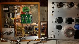
I know your frustration. Every case is unique. In my case I built streamer, AVC, and amps to work together. So streamer / DAC has RCA exiting mid box on top, so signal does not return to dirty power part of box. Then up to AVC box which sit on top of streamer. Signal then goes out the side to input of amp which fans out left and right towards speakers. So signal goes in the left side of right channel amp and speaker cable attaches on right side of amp to right speaker. Everything follows a path. Will only work in my system in my room but it works for me. Far from perfect but here is a pic with top off the DAC/streamer. Imagine a box with AVC linestage on top at the front of streamer. RCA signal goes in the back of that box then out to the amps on each side. Cables are 3" into the AVC and 12" out to each amp. Pretty compact. Keeping in 3D all the digital Rpi stuff is under the DAC separated by copper plate at front portion of streamer.
Attachments
Thanks for that...yes I find my system is becoming very bespoke and will only really work in the room and rack that it is intended for...but like yourself.. it works for me!
What are peoples thoughts on powering the Rpi with 3 separate rails bypassing the onboard switching regs..?
I have read that it gives good SQ benefits but this was with a dac hat straight onto the Pi. In using Ian's isolator and Fifo are we negating the need to improve Rpi power?
I have read that it gives good SQ benefits but this was with a dac hat straight onto the Pi. In using Ian's isolator and Fifo are we negating the need to improve Rpi power?
Greg in Mississipi has posted quite a bit of information reporting favorable results. He ultimately recommends the Allo product that has it done on board. His reporting may be on the Allo thread.What are peoples thoughts on powering the Rpi with 3 separate rails bypassing the onboard switching regs..?
Just get the usb signature, 30 on board regulated rails, job done.
Ask mrdog he has one with Ian's stack.
Ask mrdog he has one with Ian's stack.
I am planning to do the modding based on Wlowes’ suggestion.
Is it possible to open the accusilicon clock lids?
I checked and Digikey seems to have sold out the 5.4V/1.5F supercaps.
Any recommended replacement? The lower ESR the better?
Is it possible to open the accusilicon clock lids?
I checked and Digikey seems to have sold out the 5.4V/1.5F supercaps.
Any recommended replacement? The lower ESR the better?
Separate power supply for the NDK clocks, another job worth doing.
An externally hosted image should be here but it was not working when we last tested it.
Last edited:
Separatreade power supply for the NDK clocks, another job worth doing.
Agreed. If you are running a transformer IV you can make/hack another 3V3 rail from Ian's LiFePO4 board. Details in this thread.
- Home
- Source & Line
- PC Based
- IanCanada's Latest RPi GB Goodies Impressions... and your tweaks, mods and hints...