I’ve assembled LifePo4+RPi+FifoPi+ES9038Q2M+ESS Controller +Standard I/V and installed Volumio on the Pi. All looks to be ok, except there’s NO music when I play a track. ESS controller displays appropriate signal etc, just no sound from my hifi. Any thoughts to help a noob.
Agree that you might have the digital volume control turned down too far.
Also, can't see from the picture if you hooked up the little u.fl cable, and don't know if you set the dip switch for synchronous mode, or not.
Hello Ian of the other,
my package is at the customs office. did you put an invoice in the package?
Regards
Aronier
my package is at the customs office. did you put an invoice in the package?
Regards
Aronier
I’ve tried all volumes up to zero. The u.fl cable is not connected and toggle switches in default position for asynchronous mode.Is the volume loud enough?
Dom
Hello Ian of the other,
my package is at the customs office. did you put an invoice in the package?
Regards
Aronier
No invoice in the package but the customs declaration label shows value of contents, $50 or $100.
installed Volumio on the Pi. All looks to be ok, except there’s NO music when I play a track.
In Volumio - Settings- Playback Options - what have you set it to ?
Output Device - Generic I2S Dac
I2S DAC - on
DAC Model - Generic I2S DAC
In Volumio - Settings- Playback Options - what have you set it to ?
Output Device - Generic I2S Dac
I2S DAC - on
DAC Model - Generic I2S DAC
Yes, Generic I2S DAC/ON/Generic I2S DAC
I’ve assembled LifePo4+RPi+FifoPi+ES9038Q2M+ESS Controller +Standard I/V and installed Volumio on the Pi. All looks to be ok, except there’s NO music when I play a track. ESS controller displays appropriate signal etc, just no sound from my hifi. Any thoughts to help a noob.
I'm no expert but I think your IV stage might not have enough power. You should connect it's 3 connections to two outputs, the center (GND) has to be connected to a + and a -. See this page for the correct way.
Just my two cents, hope this is an easy fix.
@Maui,
I think @Domg has the IV stage power connected correctly based on the pictures. I see that + of J4 is connected to the - of J5 to make them a +-13.5V supply. Then the negative of J4, the positive of J5, and the connection between J4 & J5 (now the center-tapped ground) look to be connected to the right positions on the IVStd board.
@Domg, I was also going to say turn the volume up too, but you've responded to that.
Have you checked the voltages at each input to the RPi - FiFoPi - DAC - IVStd stack? Also the output offset voltage of the IVStd? Also check the voltage offset from ground at the + & - of the balanced outputs.
Do you have another RPi DAC that had worked before?
One thing to try is to put the DAC board + IVStd directly on top of the RPi without the FiFoPi (of course then you have to power the RPi via the microUSB or the GPIO pins).
AND you can also test the outputs from the DAC board without the IVStd by using a coupling cap in series with each channels' + & - phase one at a time (right +, then -, left +. then -... see the schematic for the correct pins) for the hot and connect to pin 5 or 6 for ground.
BUT your setup does look right and you've answered all the questions so far with the right answer. My gut feel now is something in the Volumio setup, but I don't use that and can't offer any learned suggestions.
Greg in Mississippi
Last edited:
Put the ufl in and turn true sync on. Abd refresh your sd card and power up again. Mine was the same until I refreshed and added mclk
I’ve tried all volumes up to zero. The u.fl cable is not connected and toggle switches in default position for asynchronous mode.
Dom
I suggest you buy the cheap AstroAI Digital Multimeter TRMS 4000 with a Frequency Test. Using the Frequency Test you can measure the I2S output of the FifoPi and ES9038Q2M separately to know the FifoPi and ES9038Q2M are functioning properly.
If it is an sd card or other setting problem, you should not see the normal I2S frequency value using the Frequency Test.
I2S - Wikipedia
Last edited:
@chi0001,
Not Ian, but yes that will work.
Greg in Mississippi
great, thanks greg.
HDMIpi List :
1. JoeyDD: transmitter x2, receiver x2
2. JimS: Transmitter x1, receiver X1
3. Big Bird: transmitter 1x
4. myint67 receiver 1
5. linh0983 transmitter x2
6. lindamar: transmitter x2, receiver x2
7. Lucser: transmitter x1
8. flyboi : transmitter x1, receiver x2
9. mksung: transmitter x2
10. pierantonio: transmitter x1, receiver x1
Hello Ian!
The delivery has arrived well!
I have a big problem with FifoPi!
I built everything together according to instructions!
RPi + FifoPi + ES9038Q2M + ESS Controller + Standard I / V
It worked perfectly for about 10 minutes, then the music stopped suddenly no sound, I tried all possible settings! When I start music in Volumino, the Xo Clock's LEDs flash alternately quickly. But no music.
without FifiPi, the Dual Es9038 works well.
Microsoft OneDrive - Photos
Last edited:
It looks like you are sharing a power supply between the DAC and FifoPi, when playing higher bitrate music the power consumption of the DAC and FifoPi increases so maybe check the voltage coming in the FifoPi to make sure your supply is not running out of juice.
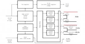
LifePO4 MKIIPowerSupply Direct to Dual Mono DAC HAT: DVCC-VCCA-AVCC Power Connections
I have 2 LifePO4 MKII PowerSupply boards. I soldered jumper pins on the bottom and battery holders on the top. I can choose V-Out easily this way.
I'm running the RPi > FifoPi > Dual Mono DAC HAT > LL1544a IV Board.
I'd like to deliver 3.3v to DVCC-VCCA-AVCC directly from the LifePO4 MKII.
What do I do with the DVCC-VCCA-AVCC Cut Out Boards?
Some have pulled them out, some say cut a trace, is there a 5.5v Supercap that needs implementation here?
Help appreciated.
Aguaazul
It looks like you are sharing a power supply between the DAC and FifoPi, when playing higher bitrate music the power consumption of the DAC and FifoPi increases so maybe check the voltage coming in the FifoPi to make sure your supply is not running out of juice.
I tested but no change! when I set (Sync mode stop DPLL) the two output LEDs of Dual Ess light up red!
I tested but no change! when I set (Sync mode stop DPLL) the two output LEDs of Dual Ess light up red!
If I'm not mistaken, ture sync mode requires specific MCLK for each FS (128*FS) which means that for a 45/49 MHz clock combo you will only be able to play PCM 352.8/384 KHz music and nothing else. No DSD either.
Agua I've just soldered in 5v supercaps directly to the pads after the pop out cap boards. I have the Ldo's bypassed, so its basically 3.3v battery power into the caps.
Sounds good to me.
I'll try 3x external 5v into local TPS7A4700 regs and supercaps next week. I'm not expecting much difference though.
Sounds good to me.
I'll try 3x external 5v into local TPS7A4700 regs and supercaps next week. I'm not expecting much difference though.
- Home
- Group Buys
- Ian asynchronous I2S and S/PDIF FIFO KIT group buy