So far, the most important aspects of this thread...
I talk about what I am doing, knowing I am the "best", "without peers"...(well, let's go with that for now😳)
Ed says "eventually you will see the problem".
I sh#t in my pants, wondering what I missed, something obvious of course..
He's bustin my chops, I'm fair game... course, I still worry about missing something...
I will carry through on the case build, but have been thinking about the speaker case build.
I have been thinking about how to measure the wall stiffness of the cabs. I've been considering how to measure force vs deflection for the materials I will be comparing. I will be using a standard 12 inch by 3 inch coupon, and setting up a force vs deflection measurement system. Maybe 1/2 lb increments vs deflection. I was thinking of putting a spring into my 12 ton shop press to control down force, with a scale to measure. Graphs will be mandatory!!
Materials include 1/4 ply, 1/2 ply, 3/4 ply, 1/2 styrofoam (high density stuff), foam covered with 9 oz glasscloth with west system resin one side, and both sides.
Then, a test using a box fabricated using four sides of 1/2 foam covered glasscloth, two at 12 inch by 3, with a cross brace (probably graphite tube because they are so cool) and 1/4 spreaders over the face. Expectation for that design is that the force/deflection will be half that measured as the center of the bracing member is zero deflection, so measured deflection will be half measured to compare identical units.
It's a shame I still work, I have so much fun doing this stuff. Alas, work pays for this stuff..
John

I got rid of my CDs.There's nothing wrong with old tech. Im still a fan with my thousands of CDs ..
My turntable kept skipping on them.
I think I kept a couple of Centronics printer cables last year when I gave away the rest. Also got a couple of ATA hard drives laying around, can't help you with the ISA, that's really loooooooooooooooong gone....
I was shocked to find the price of the 1450 is now in the 900 dollar range. Holy mackeral.
...
PS. "dinosaur"... You sound like the kid I told them to hire to replace me. World SOTA machine (25 years so far), 100 MHz pentium, 40 meg hard drive, ISA bus to motion control cards, no USB interface, only CD, windows 95...Where's the problem? It works, so don't fix it.
Course, the hardware is 30 years old. And the software isn't taught in school anymore. What is this C sharp, and how do clouds help???
...
You might need to make an End Of Very Long Past Life purchase.. https://www.rtd.com/PC104/UM/bridge/BRG17088-M.htm
The machines at work were beyond SOTA in 1996, and are still beyond SOTA now. What was done 20 years ago is still beyond that which anybody else can do. Nat. labs, big industrial companies, doesn't matter, many have tried, all have failed.
The guy I asked them to hire is using hardware and software from this millenium to upgrade the machines.
And yet, with quarter in hand, I still cannot make a phone call. Taint any phone booths!!
It's actually not the machines, but the algorithms built in that make it impossible to duplicate.
I would love to claim ownership of the success of what was done, but it was many.
John
If shop press is hydraulic, you only need to know piston diameter and pressure on gauge. Piston area*pressure=force. I know a problem; the jack in my Carolina bearing press had no port for a pressure gauge.I have been thinking about how to measure the wall stiffness of the cabs. I've been considering how to measure force vs deflection for the materials I will be comparing. I will be using a standard 12 inch by 3 inch coupon, and setting up a force vs deflection measurement system. I was thinking of putting a spring into my 12 ton shop press to control down force, with a scale to measure.
Displacement is of course a dial indicator.
Record player stylus, or similar LVDT, will also work.
Or you can go high tech, a laser illuminated at angle to etched film.
Take photos or movies, the changing pattern will give you displacement.
You must do a frequency sweep, see what happens at different frequencies.
Or simply stick an old CD, it gives nice reflections.
Or you can go high tech, a laser illuminated at angle to etched film.
Take photos or movies, the changing pattern will give you displacement.
You must do a frequency sweep, see what happens at different frequencies.
Or simply stick an old CD, it gives nice reflections.
JN,
To measure force you might try a spring scale similar to ones used to weight fish.
You could use an adapter of some source to preload it and place it online with the source of force.
But I would attach it to the other side of the piece under test and preload it. Thus the load should decrease by the force applied. Of course the preload should cause a deflection to start things off.
But a simple useful test would be to just place a woofer on the panel, measuring deflection as you sweep frequency. Then you can try to work out the contribution from the woofer by itself.
Of course I just use a rubber mallet to tap loudspeaker enclosures and measure the results with my ears. It should result in a dull thud. Any drum like sounds are a bad result.
Another worry for you, did I really spot something and am funning you even more! 😉
My thinking is this. I will make test coupons 12 inches by 3 inches. I will support these on a pair of 1-2-3 blocks, or if need, make a u shaped holding fixture using 3/4 ply to gain height. Pressure will be applied by using my shop press, but putting a spring between the press and the coupon. That way, I can control the force much better. The entire setup will be on an aluminum plate, that will sit on my scale. All I do is zero the scale for the apparatus weight. Just need a spring that will require 20 lbs to deflect say half an inch. That way the press only needs half inch travel.
I'm thinking no more than say 10 or 20 lbs . I will use one of my indicators, the tiny one with 1/2 mil increments, touching the underside center of the coupon.
Test results will be deflection vs force.
things to try:
1/4 ply (expectation is fairly low, this will be the "unit" of stiffness measure)
1/2 ply (expectation is this will have 4 units of stiffness)
3/4 ply (expectation is 9 units of stiffness
1/4 ply with diagonal ribs of 1/4 ply glued to it. (No clue as to what this stiffness will be, nor any of the experiments below🙂
1/2 closed cell styrofoam
1/2 styrofoam with 9 oz glasscloth one side using west system epoxy (test both directions)
1/2 styrofoam with two sides glasscloth using west epoxy
1/2 styrofoam two sides with diagonal ribs of 1/4 ply, glasscloth and resin to bond them to the coupon
My thinking is that the thickness of the styrofoam will cause the bottom glasscloth to go into tension, and the top into compression, fighting the force.
Ribs will be very effective at stiffining as the rib edge furthest from the foam will be resisting the tension the most.
It is also these ribs that I will couple across the cabinet, perhaps with a half inch diameter carbon fiber/epoxy tube with end slits the ribs slide into, glassclothed to the ribs with epoxy.
Remember, all I have to do is get the panel resonances high enough that the absorption fill prevents exciting the panel resonance.
John
John
There is a building material called Aluminum Composite Panel, used for cladding.
Quite rugged.
Check it out as well.
Quite rugged.
Check it out as well.
It's a cheap northern hydraulic 12 ton press. The 12 ton bottle could not hold pressure overnight, got what I paid for it of course. I put an 8 ton, 30 year old bottle in it's place, and no port for a gauge that I can remember. Bought it to make 8 inch square hardwood blanks for wooden clock gears, layering three sheets of various hardwoods for contrasting color, with grains rotated 90 degrees at each layer. It was important to alternate grain direction as well as use an odd number of layers, and also have the middle sheet twice as thick as the top and bottom so the volume of wood grain in each direction was the same. Failure to do that or keep symmetry would result in a pringle shaped gear as the wood ages. When I pin route the holes and teeth, the freshly exposed wood tends to adjust to the environment, so moisture causes the wood to change dimension, with along grain and against grain changing differently.If shop press is hydraulic, you only need to know piston diameter and pressure on gauge. Piston area*pressure=force. I know a problem; the jack in my Carolina bearing press had no port for a pressure gauge.
Displacement is of course a dial indicator.
Used a Carver press at work, it had a gauge on it calibrated exactly, I used it for compressing diodes in their housing up to 12,000 lbs. For my need here, I'll just go with the kitchen scale I bought for mixing epoxies and silicones.
John
A quick update.
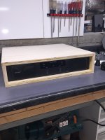
Picked up an NX3000. 7.7 lbs.
The new box weighs 5.3 lbs. Amp in box is 13 lbs.
The old BOX weighed 15.3 lbs. I tried to weigh the rmx 1450 using the kitchen scale in the basement, the scale ran off into the corner of the basement to hide.
Online says it weighs 40 lbs. Old total amp/box weight 55.3 lbs.
I'll be giving the NX3000 a try for a while once the box is done.
As a side note, because the NX is so shallow, I can mount a rear panel with an IEC AC jack, two AC outlets, and a 10 inch long cord that powers the NX. That way, the umbilical to the mixer will be the AC cord and signal wires, perhaps 6 foot long with nylon net sleeving. I can also put another small panel in with two neutriks per channel for speakers, also two 1/4 jacks per channel, gives me setup flexibility.
Figured out how to measure the stiffness of the test coupons. I will build a frame with two openings, 12 inches wide. The scale will sit on the bottom, with the machinist jack I just purchased (amazon, to right of the case) standing on the scale. I will put the test coupon in above the jack, with side notches to hold the coupon. I will jack up so the scale touches the coupon, then zero the scale, and measure how much vertical force I am applying. The upper opening of the frame will have the indicator touching the center of the coupon, measuring deflection upward. I was thinking every lb up to roughly 20 max.
Attachments
Last edited:
Dial gauge.
I have two, one the standard big dial I use to set lathe travel, and a smaller one I use for measuring runout on the lathe and tramming of the mill. The smaller has a limited range, the larger has .001 inch increments but a lot more useable travel.
The frame, I will probably just use scrap 3/4 ply in the shop, and probably put a magnetic steel top surface to clamp the indicator to.
I am so interested in what a 1/2 in styrofoam cabinet with glasscloth surfaces can do. I suspect it is probably too fragile for normal use, but corners could be internally gusseted for strength.
Saw the other thread in construction where the guy is using resonant frequency as a measure. A rather good piece of work.
John
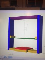
Did a quick drawing of the test setup for measuring the stiffness of the panels I will make.
The red is my small kitchen scale. The green is the test sample. It will be held up to the yellow side bars using simple clamps on the blue side supports. I suspect clamping to the yellow rail could introduce friction and compromise the measure.
When the machinist jack is placed on the scale, and turned until the jack touches the sample, then I can remove the side clamps. At this time, I reset the scale to zero. With the indicator supported from the top (purple), the indicator is set to zero on contact with the sample.
Then all I have to do is jack up until I measure 1 lb, take an indicator reading.
The beauty of it is, all the forces are between the bottom piece, the side pieces of the lower window, and the sample. Since the lower window is force driven by the jack, any deflection below the sample is unimportant to the measurement.
The only thing i would have to worry about would be any distortion of the upper window from the force. So I can put a support piece behind the sample horizontally to help lock the sides horizontally.
I can also simply put a board on the top of the side bars, and see if the reading changes as I push on the sample on the underside of the side bars.
John
Attachments
Finished up two rack boxes, a 2 RU and a 3 RU. Put the beringer 3000 and a power distro unit in the 3RU, had a gig yesterday.
Carrying the amp was just so sweet, gravity was so well behaved.
Bought some powercon connectors, going to make a power distro to go in the back of the case, that way I can put cable sets together to make setup much easier. Probably 2 powercon outs and a duplex outlet, powercon to the mixer, duplex for other powered equipment so I can control the power ground loop.
Next, the mixer case, then on to the speaker case testing and design.
John
Forgot to mention,.. used that gloppy black cabinet paint stuff, goes on with an open sponge roller, leaves a cool texture.
Worked out quite well, now the cases don't look like they were from the 80's with that grey carpet. (well, they actually are from the 80's....)
Used my XENYX 1832USB backup mixer this time, figured I was good with six mic strips in the den of a house ..sigh, five wired mics, one wireless headset mic, keyboard, bass...who knew? Shoulda brought the 2222 instead.
But ya know what made me look really cool?? 25 foot long color coded mike cables. Oh man, I rule!! The musicians all had no problem figuring out which strip to adjust. Me, I was in another room shmoozing. It was a party after all..
John
John, a question on the Powercon connectors. I got a few for my installation, but to me it looks like once you have put it together you can't unscrew it for use with a different cable. I tried - when you put it together you here a ratching sound. It looks like it is the teeth on the cable collet locking the final screw-on part.
Is that correct, or is there a way to unscrew it that I've missed?
Edit: it seems there are two families of these connectors, as luck would have it, I have the NAC3FCB-1 plug which seems to be un-un-screwable.
Jan
Is that correct, or is there a way to unscrew it that I've missed?
Edit: it seems there are two families of these connectors, as luck would have it, I have the NAC3FCB-1 plug which seems to be un-un-screwable.
Jan
Attachments
Last edited:
Jan,
Took a bit to read those directions on my phone. I have never had the problem unscrewing Neutriks. A tough go at first perhaps.
Of course you might cheat and use a classic Channellock pliers with a mating connector in a vise or panel to assist you.
https://channellock.com/pliers/
Definitely not the classic “Gas Pattern” slip joint pliers.
Last edited:
Hi Ed, I looked a bit more into the actual construction, and they are definitely engineered to prevent non-destructive disassembly.
As I also found, the older series can be disassembled, and there is a pic in the assembly guide how to disable the lock and unscrew them. That pic is no longer there in the newer series.
Attached the two assembly instructions.
Jan
As I also found, the older series can be disassembled, and there is a pic in the assembly guide how to disable the lock and unscrew them. That pic is no longer there in the newer series.
Attached the two assembly instructions.
Jan
Attachments
- Home
- Member Areas
- The Lounge
- I am unhappy to report that gravity is changing, it is no longer constant.