Jan,
I have never damaged one by just unscrewing it. Also never needed to use more than my hand force.
Of course I also don’t use a nut cracker to open walnuts.
I have never damaged one by just unscrewing it. Also never needed to use more than my hand force.
Of course I also don’t use a nut cracker to open walnuts.
Happily, the expanding Earth theory explains all this, and how the continents all fit together, however there's just the "matter"of explaining what makes the Earth expand from the inside.....
As I said, the new version can't. I can see the ratchet ridges on the collet preventing it to go the cc way.Jan,
I have never damaged one by just unscrewing it. Also never needed to use more than my hand force.
Of course I also don’t use a nut cracker to open walnuts.
Even the old version has a guide with a small arrow on the chuck where to put the screwdriver to unlock so you can unscrew it.
You have to break the new version to unscrew it. But I'll sacfifice one to try as much force till it gives ...
Jan
I purchased NAC3FCA and NAC3MPA-1, Cococina made (I guess) from Amazon, a set of 5 pairs, ins and outs with chassis jacks.John, a question on the Powercon connectors. I got a few for my installation, but to me it looks like once you have put it together you can't unscrew it for use with a different cable. I tried - when you put it together you here a ratching sound. It looks like it is the teeth on the cable collet locking the final screw-on part.
Is that correct, or is there a way to unscrew it that I've missed?
Edit: it seems there are two families of these connectors, as luck would have it, I have the NAC3FCB-1 plug which seems to be un-un-screwable.
Jan
The end shell does have eight ribs that do look like they would lock to the collet as the end part screws on. But mine do not ratchet.
Examining the collet, it has a threefold symmetry with two indents per blade that look like they would engage the ribs, but a sixfold symmetry could not engage the eightfold ribs all at the same time.
In addition, the end shell bottoms out on the body before any engagement occurs. I've tried several different cable diameters, but no ratcheting at all.
The instructions that came with them were not well written. (well, ok,,,non existent). Your linked instructions at least show blue as power in, grey power out.
The chassis connectors require 4.8mm fastons, I note that neutrik 4.8's from partsexpress (.187 inch) have a locking feature that engages the male connection hole. That prevents pulling the connection off the blade. I purchased another type that has no locking feature, but I plan on using cable clamps and a metal box that I will also bond to ground. The chassis connectors are not finger safe, so I won't just mount them into a wood panel. Back in the old days, I would sometimes solder speaker wires to the faston blades, instead of the proper connector, but for AC power, it is absolutely against code to solder the ground wire like that.
If I'm not happy with the tightness of the cheaper fastons, I'll break down and purchase the neutrik locking ones. I balked at 9 dollars shipping for a very small bag of clips costing 12 dollars and change.
John
Last edited:
While you have Free shipping for a $2 reading glasses all the way from China. How the world operate eludes common sense too often it's not possible to stay sane.
The reading glasses cost 50 cents here in the wholesale shops.
Factory gets maybe 25 cents.
They weigh maybe 20 grams, or 50 to a kilo, and the material cost is less than 10 cents.
Postage..there is some issue of the US losing money in its postal system..
But how I get 3 butane lighters for 25 cents is still mysterious, look at all the parts and labor, add shipment, those guys must be selling them for silly money.
Container load of fly racquets? 40 cents each...the battery and transformer themselves cost more than that here.
Last edited:
I had searched on amazon for the fastons. Found the neutrik NLfastons, said to self "they're mine". put them in the cart, went to buy but then saw that shipping was not amazon prime free, and it looks like it is shipping directly from partsexpress. So they're putting it in a postal envelope which is probably 9 dollars.
If I do go that route, I'll probably buy some other small items to at least load the bag up for the same price.
ps. guys, thank you for reminding me that I needed some reading glasses. Just bought them.
John
If I do go that route, I'll probably buy some other small items to at least load the bag up for the same price.
ps. guys, thank you for reminding me that I needed some reading glasses. Just bought them.
John
Last edited:
Picked up 20 pcs of 1/2 inch NPT strain relief cable glands from amazon. My plan is to make a small 2 RU height half width case maybe 4 inches deep that has a 6 foot line cord attached for use. I will also take an EIC line cord, cut it to length, and use the strain reliefs to get into the case. Also I will put a powercon "out" and some regular duplex outlets in the box for normal equipment powering...maybe I will do a GFI, one of the newer self testing types.
I will also make a powercon in-to out cable with a line signal cable, grouped using a nylon braid to connect to the mixer. Actually, two, one about a foot long for mixer stacked on amp, and another 6 footer for mixer on a stand when active control of the mixer is required.
I believe that I will have to continue working until I turn off my amazon account, my hobbies require I continue work and getting paid,. Not sure if this is good or bad.
John
True enough. But I'm not ready to pull the trigger on replacing the eminence delta 12's with neo units. I would need 4 of them, dey too expensive..
John
John
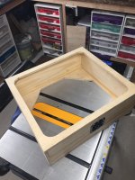
Some new work.
first pic shows the routing of the bottom and the top. I left material for the bumpers on the bottom of the mixer, the intent is to have it resting on the bumpers, while also locked by the rails on the sides. The top, I removed more for weight.
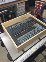
Second pic is the fit of the mixer in the bottom of the case. Note there is room in the back that is where I plan on putting the box for the powercon connection and the stereo feed to the amp using an XLR connector. On the left, I plan on some kind of relief to allow the 100 foot snake to nest, some kind of brass thingy to lock the snake and prevent pullout. Will give details when I figure it out. It will be a lathe thing, good to roughly 1 thousandth of an inch accuracy (only because I can...or hope I can).
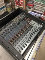
Third is the mixer locked to the side rails. I glossy black painted the inside, and did the speaker paint textured thing on the outside.
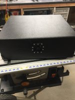
Fourth is the case closed. This is the front, a locking mechanism. On the back I used detachable hinges.
If you look closely, the locking part is setup so there is nothing higher than the front edge. I will make a pair of brass pins to locate the side edges, the sides do bow a tad relative top and bottom, and I don't like that.
I will now work on the back powercon and output box. My plan is one cable, power and stereo signal, to the amp chassis.
John
first pic shows the routing of the bottom and the top. I left material for the bumpers on the bottom of the mixer, the intent is to have it resting on the bumpers, while also locked by the rails on the sides. The top, I removed more for weight.
Second pic is the fit of the mixer in the bottom of the case. Note there is room in the back that is where I plan on putting the box for the powercon connection and the stereo feed to the amp using an XLR connector. On the left, I plan on some kind of relief to allow the 100 foot snake to nest, some kind of brass thingy to lock the snake and prevent pullout. Will give details when I figure it out. It will be a lathe thing, good to roughly 1 thousandth of an inch accuracy (only because I can...or hope I can).
Third is the mixer locked to the side rails. I glossy black painted the inside, and did the speaker paint textured thing on the outside.
Fourth is the case closed. This is the front, a locking mechanism. On the back I used detachable hinges.
If you look closely, the locking part is setup so there is nothing higher than the front edge. I will make a pair of brass pins to locate the side edges, the sides do bow a tad relative top and bottom, and I don't like that.
I will now work on the back powercon and output box. My plan is one cable, power and stereo signal, to the amp chassis.
John
Attachments
Last edited:
I would love to respond. However, I've no clue what you meant.
Picked up a can of bo-guard t-9 (IIRC), spraying all the stuff to prevent corrosion. Did 2 rows of my pin guages, will continue.
I suspect the PO for diode stuff in youngwood will soon happen, so I may be in your neighborhood soon to visit.
PS. I lament the lack of younguns to teach. The DOE dies not consider that a priority. sigh.,
jn
Hmmm, been thinking about what you said. A wrist pad attached to the front edge of the box with a piano hinge, designed to open out and provide a rest.Wrist rest pad?
Not a bad idea, I like it. I never would have thought of it, as I don't use the mixer a lot. I hafta figure out the hinge setup to allow the lid to work.
ps. It's Bo-shield T-9 I am using to coat all my tools to prevent rust.
John
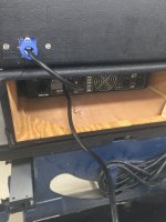
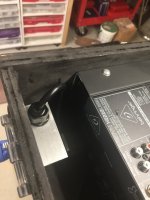
Finally added the powercon feed to the back of the mixer case.
Purchased a pair of IEC cords, one right hand, one left. Wasn't sure which would work better.
Purchased cable glands to work as strain relief for the cable in the case.
Cut the cable with about 8 inches length from the female.
Made an aluminum bracket and mounted the powercon and the gland. That would have been a real problem if f I didn't have a boring attachment for my mill. Used a unibit to get out to about .8 inch dia, but had to bore to final dimension for the powercon, roughly .930 dia. I took 5 mils per pass as I have a mini-mill, only 500 watts drive and it's not as sturdy as a bridgeport. Also funny is, I chucked the unibit into an R8 collet as the jacobs has a few mils runout. Kept the X/Y position to within .0002 inches, then ran the boring tool. I noted that the unibit didn't keep the hole round despite using the R8. The first boring pass at 3 mils cut was really noisy because it was interrupted, but subsequent 5 mil passes were quiet as can be. Honestly, I don't know how I built anything in the past, my current workshop is such a pleasure to use.
First is the mixer/amp stacked. AC feed is just long enough, the second cord is the power strip cord.
Second is showing the bracket with the line cord coming out of the gland.
This power cord is exactly long enough to stack the two, power is about 15 seconds to connect. I will just keep it in the amp case, as it's a pain to reach in and plug it into the power strip. Should I want to put the mixer on a stand, I will make another power/line feed cable set, probably 6 to 8 feet long. But most of my gigs are set and forget, I rarely find myself tracking performers.
Next I will do a small aluminum plate to add 3 xlr panel males. One right, one left, both for balanced outs... and the third will be a stereo xlr, unbalanced to feed the amp case. Given I am controlling the power/signal loop area, there will be no hum unbalanced. My goal is to take roughly 30 seconds to have a complete system setup, with another minute or so to connect the speakers. The majority of setup time will be hoofing the speakers and stands. For that, I just play the victim (gravity wise) and have others do the heavy lifting..
After that, I will machine a round adapter to clamp over the 8 mic snake I have, and figure out a nest it will lock into on the mixer case. That way, the individual mike cables that plug into the strips cannot be pulled by the cable.
John
Attachments
Last edited:
Of course I can punch a 15/16” hole in steel or most metals up to 1/4” thick with one of my hand punches. If for some reason I would need to!
Normally I would just punch the whole panel out of .062” steel with 1/2” flanges top and bottom. Much more rigid than 1/8” aluminum.
My schooling says you can’t drill a round hole. If you want round you ream it to finished size. As to chuck run out, I did have a guy named Chuck stiff me for a bit!
However in your case that seems to be a bit much and I would look for dirt or chips wedged in where they don’t belong.
Do you have a drawing of the panels you still need?
Wait, first question can you do a drawing? 😉
ES
Last edited:
Drawing??? Shirley you jest...
The angle aluminum was flexing under the unibit load. The 5 mil boring passes were far more gentle to the part.
I do indeed have a set of over/under reamers when I really need accuracy.
But I do indeed maintain cleanliness for the accurate things.
John
The angle aluminum was flexing under the unibit load. The 5 mil boring passes were far more gentle to the part.
I do indeed have a set of over/under reamers when I really need accuracy.
But I do indeed maintain cleanliness for the accurate things.
John
Being thrifty, and having $25000 in tools stolen 9/20 by my neighborhood unemployed housepainter, I make odd size round holes with a ball bit in a hand grinder. I draw the circle I want with a sharpie, then enlarge a 1/2" hole. Nothing above 1/2" drills properly in sheet metal, IMHO. Square holes I make with a carbide blade in a hacksaw.
Use safety glasses when using power tools. Boilerplate for newbies.
The owner of Weldrite, a welder dealer in zip 47129, had his ADT alarm protected garage emptied by thieves. They used a chainsaw through the roof, backed up by a gasoline carbide blade saw.
Use safety glasses when using power tools. Boilerplate for newbies.
The owner of Weldrite, a welder dealer in zip 47129, had his ADT alarm protected garage emptied by thieves. They used a chainsaw through the roof, backed up by a gasoline carbide blade saw.
- Home
- Member Areas
- The Lounge
- I am unhappy to report that gravity is changing, it is no longer constant.