ok, first thing.. this might not be correct. I hope it is 🙂
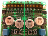
Second, zoom in using the interface (I believe you can save the fullsize images this way, if you'd like to stitch them together) and I made sure that each resistor value is readable. The only ones that might be hard are 0805 resistors that I made fit, but even those seem readable.
Still haven't found a lower profile 2-position connector (the larger ones are Molex KK) or populated the ground point between the two channels, so you'll notice this stuff is missing...
Picasa Web Albums - M - HPS
An externally hosted image should be here but it was not working when we last tested it.
Last edited:
Luvdunhill. PCB looks good , but some soldered joints should have been better made. Too much solder on some transistor legs may hide dry or cold joints.
Perhaps your solder wire is too thick.
One thing which confuses me is LMH 6321 first stage buffer. According to datasheet, max. voltage for this IC is +/- 15V. In HPS 5.1 it is used with+/- 22V.
Any explanation?
Perhaps your solder wire is too thick.
One thing which confuses me is LMH 6321 first stage buffer. According to datasheet, max. voltage for this IC is +/- 15V. In HPS 5.1 it is used with+/- 22V.
Any explanation?
@sq225917 : That is just perfect.
In the mean time i got the price estimate for the PCB's, it's 79 euros for 10 pieces, meaning i have 9 to give away at 7,9 Euros a piece. If anyone in Europe is interested let me know.
In the mean time i got the price estimate for the PCB's, it's 79 euros for 10 pieces, meaning i have 9 to give away at 7,9 Euros a piece. If anyone in Europe is interested let me know.
Indeed, I think if I were to go back I'd suck the solder off each part afterwards to try and reduce the amount of solder. I'd agree it's perhaps a bit thick for those transistors, but suitable for the rest of the parts. It's amazing how much less solder you use with SMD compared to TH.
Indeed those parts are inductors. Here's the datasheet for the part I used:
http://industrial.panasonic.com/www-data/pdf/AGA0000/AGA0000CE24.pdf
Good question about the LMH6321. Perhaps the LT1010 is a better choice, or placing a zener between each supply pin on the LMH6321?
Indeed those parts are inductors. Here's the datasheet for the part I used:
http://industrial.panasonic.com/www-data/pdf/AGA0000/AGA0000CE24.pdf
Good question about the LMH6321. Perhaps the LT1010 is a better choice, or placing a zener between each supply pin on the LMH6321?

Good question about the LMH6321. Perhaps the LT1010 is a better choice, or placing a zener between each supply pin on the LMH6321?
Or changing R403, R412 to 680 Ohms?
P.S.
Or if you like to push it to the absolute maximum ratings you can leave R403, R412 at their original values for a calculated +/- 18 volts first stage supply
Last edited:
Never mind mount them straight I sure as hell can't solder the resistors on without trashing them in the process. So I've stopped the build for now.
What's the chance that some kind soul with the requisite soldering ability would be prepared to take on the fine task of soldering the resistors and SMT caps onto this board for me. I'm going to end up destroying this board if i try it myself.
Happy to pay for your time etc.
What's the chance that some kind soul with the requisite soldering ability would be prepared to take on the fine task of soldering the resistors and SMT caps onto this board for me. I'm going to end up destroying this board if i try it myself.
Happy to pay for your time etc.
If anyone has used the BOM I worked on please be aware that I only listed components for 1 channel of the power supply,sorry.
Yeh, helps me realise I'm out of my depth with the components. All the resistors that i've put on the board so far don't measure right on the board. They measure fine lying on my bench but once they are soldered, nada.
What solution have the other HPS5.1 builders come up with for the mains power supply? A nice PCB would be good, somthing to fit 2 surface mount transformers and the other components. Nearly there now and my Cartridge arrived today 🙂
also what caps are people using for the 100n caps
I'm using ROE MKP1837
Right, I am royally giving up on this one, it's just utterly beyond my ability to solder together.
I'm using ROE MKP1837
Thanks, the search function let me down.
Sorry to hear you are giving this one up sq...🙁
Well both sides of mine are now constructed. i need a PSU and then we can take some accurate measurements.
Does anyone have know of a pcb for the PSU which I can fit two PCB mount toroids on?
They measure fine lying on my bench but once they are soldered, nada.
You know that when you fit the resistors on the board, they end up in series or in parallel to eachother, so most of the time you can't measure their own value anymore?
You know that and I'm only misunderstanding you, right?
Have fun, Hannes
You aren't misunderstanding me, these are a pair of resistors, one per side of the board, measuring nada...
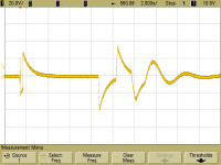
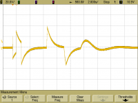
On start up there are some horrible transients on the outputs for about the first 20 seconds; after this some low level, low frequency oscillation still happens but it settles down.
Has anyone else experienced this, I wouldnt want it connected to the amp with this!
Has anyone else experienced this, I wouldnt want it connected to the amp with this!
Attachments
- Home
- Source & Line
- Analogue Source
- Hps 5.1