Hi Kay Pirinha,
I remember your schematic from post #70 in this thread: https://www.diyaudio.com/forums/tubes-valves/178773-el509-jj-pl519-7.html#post5368094
Could you perhaps take a picture of the amp and a separate one of the PS. I can’t make out some of the resistor values in the combined photo.
Bas, also take look a the Synola design. There are more references in the mentioned thread.
It is funny that a more advanced design is dismissed just because it is not understood and a more simple way is chozen but then asking here why it does not perform.
Bas, also take look a the Synola design. There are more references in the mentioned thread.
Here is the latest incarnation of the Synola design I know of in post #95:
https://www.diyaudio.com/forums/tubes-valves/178773-el509-jj-pl519-10.html#post5963027
However, not sure where the EL84 cathode resistor connects to ground. Help anyone?
Last edited:
You asked for it....
In the original design of Bob Danielak you see a feedback loop. This has more then just one function (it is also a bootstrap). But nobody here likes this way and thinks that they can do better but nobody can get close to 10W out of the amp.
Please also read his statement :
Quote from Bob:
(Please note that constructing this amplifier requires some
technical skill; therefore, it is not recommended as a DIY project for the novice.)
I know some here are no novices but somehow act like one asking the same question again and again over the years in several threads even, and not yet have figured it out after all these years
I am sorry, normally i do not reply that harsh, but you asked for it.
Best regards,
Frank
Here is an other approach (see attachment).
This is how i would do it (off topic as it is not "enhanced" mode but true triode with EL509 tubes or 6LF6).
But be carefull as it can byte you (Plus 720V and minus 145V are required).
It is a push pull version but can be easily converted to SE.
Here you can use a small tube to drive the screen as not much current will flow (as it is negative instead of positive charged)
Good luck and have fun !
Attachments
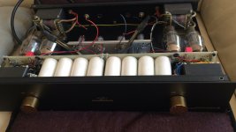
A project i did for a friend:
"Brocksieper Music Components Schmendrick"
After the mod this thing really rocks!
Screen grid driven with very low bias voltage as grid 1 is now shorted to cathode.
+650V anode voltage fully balanced design.
"Brocksieper Music Components Schmendrick"
After the mod this thing really rocks!
Screen grid driven with very low bias voltage as grid 1 is now shorted to cathode.
+650V anode voltage fully balanced design.
Attachments
![PARZ9133[1].JPG](/community/data/attachments/835/835726-4515bed0affa6606a12dc74ff8801cbf.jpg?hash=RRW-0K_6Zg)
![DYVS9438[1].JPG](/community/data/attachments/835/835735-0fd2cbd37fdd482a18aaf7ba932fce37.jpg?hash=D9LL03_dSC)
Last edited:
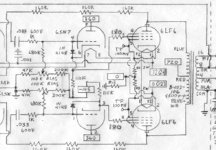
Hi Lampie!
Your scan is one of the amps by Berning, operating with very low current (10mA). So for SE It would need some other operating points.
Your amp looks nice! Are you willing to share a schematic?
Your scan is one of the amps by Berning, operating with very low current (10mA). So for SE It would need some other operating points.
Your amp looks nice! Are you willing to share a schematic?
After all it is the “Do It” yourself forum!
I am sorry, i do not post any schematics as i use them commercially (now or in the future).
The Berning amp was just to show that it can be done in a different way and that it looked to me that this thread got nowhere (linking to already existing threads talking about exactly the same).
I am sorry, i do not post any schematics as i use them commercially (now or in the future).
The Berning amp was just to show that it can be done in a different way and that it looked to me that this thread got nowhere (linking to already existing threads talking about exactly the same).
Perhaps I should mention that I'm planning to use the el509 by JJ. And at 270V on the plate and at 150mA. Since that has been done with the el509 and UBT-1. So any dc coupled examples are not a shoe in for me. I'll just go with power drive/source follower...it it the same thing?
Casccoded CCS where I would use the mu-follower output be sufficient to drive the EL509 in enhanced triode mode?

As long as the driver is able to deliver 10mA to the screen grids you should be fine. I like to use PCL85 or similar for this job as it can deliver enough current at low voltages to drive the screens.
Last edited:
Perhaps I should mention that I'm planning to use the el509 by JJ. And at 270V on the plate and at 150mA. Since that has been done with the el509 and UBT-1.
Bas,
If you have it, could you provide a link/reference to the EL509/UBT-1 at these operating conditions, please? UBT-1 specifies 160ma max.
Following this with great interest and wish you the best. I have a pair of UBT-1s sitting idle, as well as several NOS 6KG6as.
10mA to the screen not in total !
I would sell the 6KG6 tubes and buy a double amount of EL519 instead or trade. Not because there is anything wrong with them but there are people who have amps using these tubes and having difficulties getting replacements as the sockets are different. In many cases replacing the sockets in not an option.
Just a thought...
Attachments
- Home
- Amplifiers
- Tubes / Valves
- How would you drive an EL509 in enhanced triode mode.