And then we can discuss that the grid leak resistor at the output tubes must be matched. And if one uses fixed bias, the output impedance of these vary with the potentiometer position. Morgan Jones therefore buffers the output of the bias circuit in his latest PP amp. And so on and so on...
jderimig,
Unless you want to re-design the amplifier, the quickest solution is to get pairs of tubes that match each other reasonably well.
I do not consider one tube at 2 mA/V and a tube at 3.8 mA/V to be a good match.
Normally, plate current is much larger than screen current in all but the ohmic and transition regions of the pentode plate curves.
So, that means even with two tubes that have a little mis-match of screen signal current, the plate signal currents should still be close to equal.
Just be sure the signal swing does not take the tube into the ohmic and transition region of plate voltages on the set of plate curves.
And, if there is a fair amount of global negative feedback, most of the errors of a mismatch will be covered up anyway.
This thread is about 6CB6 Pentodes not triodes.
I think I discussed the plate amplitude match when using Triodes, Versus . . .
the plate amplitude match with pentodes, which can be different, because of the screens.
With Triodes, Kirchoff's law is easy to apply, the loops are simple and well defined, when there is a really good CCS, and no control grid current (and no screen in a triode).
Do not let fear stop you.
Build the amplifier, find reasonably close matched 6CB6 pairs, and enjoy the listening sessions!
Last edited:
Agreed......Some power tube amp designs from the 1970´s tried to compete with the newly horrid sounding transistor amp by having only 3 stages; however the massive gain from true pentode CCS as drivers nearly always required a balancing pot in the anodes to match the drives versus distortion, and woefully missing was the valued CCS in the tail, as was then a high value resistor. So we have a massive variables. To cap these problems, some designs used 30dB global nfb to make up for the misbalanced tube stages....so there we leave it. It doesn´t sound that bad after all! Tubeamp designers knew manaufacturers selected their tubes on a one-out-of-three basis so worst case mismatch could be avoided. However the glass TV market where distortion wasn´t an issue was otherwise; expect a 50% toleraance on all parameters, except perhaps the heater current.jderimig,
Many do not want to believe that a properly designed triode pair and CCS LTP has a perfectly good [amplitude] balance.
Very badly unmatched tubes can cause problems, but only in the case of:
one tube running out of dynamic range (plate voltage swing)
one tube's grid to cathode voltage becoming equal to the "contact potential".
When only one grid is driven, you have to pay attention to the other tube's un-driven grid versus its moving cathode voltage, so that it does not cause the grid to cathode voltage difference to be at the 'contact potential' voltage.
So how far does the cathode of the tube with the un-driven grid move?
This far . . . the direct connected cathode pair's signal voltage swings just 1/2 as far as the input grids signal voltage.
Kirchoff's law has worked perfectly during my 78 years of life. It still is working.
Have Fun!
Use good CCS LTP circuits.
That is a solid reason I use high gm pentodes configured as triodes to get some sensibility out the misbalances also with modest gain. It works for me and I am quite happy to have a 25dB gain triode LTP ending up with good matched stages not requiring a pot in th anodes and a little global nfb and leave it to listen to.
Bench Baron
In my experience having built quite a few PP valve amps which all use a LTP with a CCS I've found the DC Va are always mismatched by about 10v but always have equal AC out. All my CCS's are adjustable within say +/- 10%, I've found it makes little difference THD wise or CMRR wise.
I've made a few amps with adjustable bias supplies whereby I can null the OP stage quiescent DC current & tried using adjustment pots as part of the LTP anode resistors and other adjustable AC/DC parameters but found it makes very little difference in terms of THD, CMRR etc. Sure, I can measure small differences, but we are talking tiny amounts of change, non of which I've been able to hear.
Conclusion, don't worry about matching triodes in double triode valves, that way madness lies.
Andy.

Not to hijack this thread but I´ve lost track over a forum mail (I think it was you who did it; but anyway, this one can serve as a reminder) regarding amps using completely separate neg supplies.....there is a risk adopting this method as it uses far more components when compared the simple method of the mains transformer secondary/tap which has fewer components.
Watch out when using an independent neg supply from a separate transformer. On my powerful 8 tubed fixed bias KT90 amp having very large current swings, the dreaded orange anodes scenario appeared on all tubes. It was short lived as one detects the whiff of hot dust.
Problem:- The separately powered neg line was dragged down by a faulty Zener (TL431), resulting in excess B+ anode current which did not blow the modestly rated B+ fuses. To get 8 anodes of large KT tubes glowing orange requires an uncompromising power supply with grunt. So, now arises the scenario of selecting a proper fuse to save all including the output tranny.
This bias failure scenario might apply to anyone´s favourite power tube series; but dealing with real power and to deal with a partial or complete bias fail, I use an interlock cobbled around a LM393 or sim window comparator that samples a defined negative and B+ positive volts. An SCR can act as a disable relay latch /i.e relay opens on fault. Naturally, a faulty tube leading to sparks or orange run-away won´t be protected from this, but since the chassis uses 8 x KT90´s, some ½ intelligent protection is necessary.
Ingenuity can work wonders.
From my past experience, fast fuses marginally rated just over the maximum circuit current do wear out and need replacing regularly, an annoyance. An output tranny designed for parallel PP will have quite a low primary resistance on each half, so chance of damage is very small.
The old bias fail circuit shown in the GEC KT88 100W amp which uses a relay with triode held at cutoff;... when activated, will open a common cathode resistor is quite a poor method; as a part dying bias failure will result in relay chattering with horrendous loudspeaker chatter.
Bench Baron
benchbaron,
Glowing KT90 tubes?
A brief "hijack" of the thread, should be OK.
How about a different design for those who are just building a new amplifier with multiple output tubes?
Self bias . . .
1. Advantages:
Simplicity, reliability
The failure modes of Individual Self bias for each output tube:
Open resistor for one tube (no quiescent current, and no signal current) (*)
Open bypass capacitor for one tube (lower signal current) (*)
Shorted resistor (*)
Shorted bypass cap (*)
() Select properly rated and good quality parts to prevent ()
No negative supply required
Easy "plug-and-Play" current sharing for tubes that are in the same ball park, does not require super matched tubes.
This tends to protect the output tubes, and it is easy to measure the current of each tube (a mA meter, series resistor, and a multi postition switch that connects the series resistor and meter across the self bias resistor.
There is no "plug and Pray".
No bias adjustment pots required.
2. Disadvantages:
Requires lots of self bias resistors, lots of bypass capacitors, and lots of room (real estate) under the chassis.
The bypass caps will charge, and bias voltage will increase with music such as long sustained 32 foot organ pipe notes.
Higher B+ voltage is required, for the same power output.
3. I hope I have covered most of the tradeoffs of self bias.
4. I will let someone else discuss the advantages and disadvantages of using fixed bias, and fixed adjustable bias, such as your amplifier that is giving you trouble.
If you do not need the full power of your amplifier, you might consider using Individual self bias for each KT90. They are very Expen$ive!
Have Fun designing, building, and listening
Last edited:
Yes, quite right..(sit back and yaw at the next bit!)..Worth the risk in fixed bias ?... I know, but I´m in the power audio game and you are correct; design down to lowest pedal notes requires grunt sized transformers and rather large studio drivers. As you mention the decoupling cap in each autobias output stage cathode is an unwanted pole hindrance at lowest frequencies but is sort of self protective.
There is more and more (awful) digitally reproduced music around with fast attack rise times especially bass beat notes that are a good test for tube amp global feedback loop stability esp. those amps with poor loop damping settling. This shows up in the twin freq SMPE 4:1 intermodulation distortion measurements, but the frequencies selected typ 50Hz/6Khz I feel need updating as there is far more LF content in today´s programs. 50Hz was a suitable low SMPE frequency in the 1950´s but loudspeakers have improved enormously and far more lower frequency content is in music these days.
It is well documened that the traditional Williamson 50W amp design interstage components fail on long time constants that lead close to LF instability. I am currently doing a new global nfb alignment that takes the selection of the these interstage R/C components more closely to avoid unnecessary loop under and overshoot, i.e optimized Q. I´m not rewriting, but burning midnight oil -> complex maths is on. Sound tests etc all to come.
Bench baron
What about "hybrid bias"? Cathode resistor + cap and negative bias, enough to have some of the benefits of self bias, but reducing heat dissipation?
Exactly. With equal plate loads this certain point is defined by unequal maximum signal swings.The tail CCS will balance the LTP output AC voltage even with mismatched tubes. Up to a point, of course.
Best regards!
I remember having read that the trimpot (sides to the LTP cathodes, wiper to the CCS) is detrimental to the ac balance of the LTP.The tail CCS will balance the LTP output AC voltage even with mismatched tubes. Up to a point, of course.
So it would be better not to have it, and select a tube with similar mu on the two triodes instead?
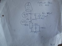
Yes and no, zintolo! Yes to the superfluous »balancing« trimpot, no to the necessitiy of similar µ triodes. For example, the circuit in #16 works well even with a 12AX7 and a 12AU7 triode, at least until one of them, probably the 12AU7, runs out of juice.
Best regards!
Best regards!
Wouldn't ac balance issues show up in THD (namely 2nd) measurements? Or use the trim pot to minimize THD ala PMillett?
With a CCS tail and equal plate loads there won't be any AC imbalances.
Best regards!
Best regards!
This is true for pentodes. In triodes there is a voltage drop on rp. In case of unequal Gm and mu, this rp is also different, so the output voltage is different.With a CCS tail and equal plate loads there won't be any AC imbalances.
Best regards!
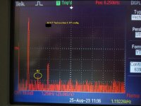
The trim pot is okay with the one out of three tube variations. Yes, H2 would null out using top notch matched sections, i.e 6CG7#6SN7 as front end with 22K anode loads #350V B+ and common cath anchored by neg -15V LTP (7mA each section), provided the following spectrum below. Same spectrum up to clipping.Wouldn't ac balance issues show up in THD (namely 2nd) measurements? Or use the trim pot to minimize THD ala PMillett?
Note with near perfect section matching H2 has dropped to insignifigance. I can thoroughly recommend this as a starting point. For those without digital FFT scope access, a clue to the degree of matching between sections is to monitor the common cathode with a scope, when one should see a diminitive amount of H2 with best balance.
When this is feeding a highish gain power diff driver also with LTP in common cath to force balance with cathode to grid feedback, one can expect a superlative performance. Finally, a power stage finalized with modest amounts of global NFB will deal with H3. The rest should sound good.
Simple ain´t it.
Bench Baron
Attachments
The current through each plate load resistor has to be the same, no? If not where does the unbalanced current go/come from?This is true for pentodes. In triodes there is a voltage drop on rp. In case of unequal Gm and mu, this rp is also different, so the output voltage is different.
Taa, ...........Deep in my old notes I might re-visit this config again. Could be a candidate-What about "hybrid bias"? Cathode resistor + cap and negative bias, enough to have some of the benefits of self bias, but reducing heat dissipation?
As 6A3 mentions Loose some power. Sacrifice 50V so Power output would drop to 100W (parallel pairs) with 500V B+. How awkward, as I am currently using 500V electrolytics with a B+ of 450V to give 120W. (I hate doubling up electolytics, it wastes space just to get headroom voltage conform).
Bench Baron
- Home
- Amplifiers
- Tubes / Valves
- How well do LTP driver tubes using CCS need to be matched?