I think you are measuring from one output only to ground and thinking voltages. In which case, with an unchanging current through the LTP, the anodes just bounce up and down, with zero attenuation at each anode. But if you measure differentially, things are a bit different with respect to a hostile signal injected onto the HT. Provided the two valves are identical (intrinsic in SPICE), there is no differential signal. However, if you use two very slightly different SPICE models (I used 6J5 and 6SN7GTB) a much larger differential signal appears. But a 6SN7 is just a dual 6J5, so that test was effectively two slightly mismatched devices. Beware that often the same model is given different names, resulting in -300dB signal (that happened with 6J5 and 6SN7). Given that we often use a LTP to drive a push-pull pair, measuring differentially is important.Huh? The PSRR of the LTP is basically unity, whatever happens.
I mean yeah if you think reality is ever gonna match SPICE. But since 'tuning' the matching of the two valves is rarely within our gift (most people use dual triodes), we just have to take whatever differential PSRR reality gives us. Signals on the PSU are small, and when multiplied by the imperfect-but-OK differential PSRR of the LTP (where audio signal levels are high) is still going to be an excellent SNR. Certainly swamped by noise from earlier sources. So I disagree, measuring differentially is not important, it's just a thing you can do in SPICE as an academic exercise; there's not much you can actually do about it in practice.
Last edited:
I found this a excellent way to understand the LTP.One way to imagine the LTP with perfect current source and mismatched valves is to imagine "unraveling" the LTP by removing the load impedance of the undriven side from B+ and connecting it to ground (pretend that the valve could still work!). What we have left is a strange split-load inverter, which we've long accepted as output matched if the loads are matched.
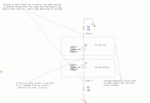
Attached is a diagram of the AC circuit with the DC circuit stripped out.
The triodes become simply a source of AC voltage.
The CCS are removed from the AC circuit due to it's very high AC impedance.
The resulting circuit is so very simple to understand.
Two voltage sources in series with two load resistors in series.
The voltage on both load resistors will be the same as long as the load resistors are the same value.
Any complexly of understanding this circuit in practice comes from interactions injecting unexpected AC currents into the central floating node between the two triodes. This can be from imperfections in real CCS sources or stray capacitance.
If you want to see what different Rp will do they can simply be added in series with the voltage sources making it still a very simple series circuit to understand. Or change the voltage sources to current sources with parallel resistors. The simple series nature of the whole is unchanged.
Attachments
Last edited:
Can I add one variable that has often been debated and never discarded or approved totally?
The balancing trimmer on cathodes of the LTP: wiper to CCS and each extreme to one side of the LTP.
Can someone argument it?
The balancing trimmer on cathodes of the LTP: wiper to CCS and each extreme to one side of the LTP.
Can someone argument it?
In SS amps this trimmer adjusts DC offset. Didn't see it too often yet, for not to say never, in tube amps
Best regards!
Best regards!
The added resistance degrades total stage gain. That may or may not matter to you.The balancing trimmer on cathodes of the LTP: wiper to CCS and each extreme to one side of the LTP.
The trimmer does allow the balancing of the DC voltage on the load resistors if the tube match is poor.
It does nothing to balance the AC voltage if a high impedance CCS is used.
Setting it off center will lower AC gain in one tube and increase the AC gain in the other tube but as they are is series this does not affect AC signal balance at the load if a high impedance CCS is used.
The trimmer does nothing for common mode supply rejection if the CCS is high impedance. Again it is all a series circuit.
It can be a useful balance trim when a low impedance CCS or simple cathode resistor is used. I prefer putting any the trim in the plate circuits but that is just me.
It can improve common mode balance or make it much worse from current injected into the center node of the two tubes from stray cathode capacitance or a low impedance in the CCS.
As I am always looking for extra gain I have not used cathode trim pots.
- Home
- Amplifiers
- Tubes / Valves
- How well do LTP driver tubes using CCS need to be matched?
