I asked this in the DCPP thread but will post here for larger group.
How well do the driver tubes have to matched in this design? I suspect it's not that critical due to the CCS. Using my utracer my first set of 4 6CB6's gm ranges from 2 to 3.8 mA/V. Otherwise I can still balance the bias levels with the trim pot.
How well do the driver tubes have to matched in this design? I suspect it's not that critical due to the CCS. Using my utracer my first set of 4 6CB6's gm ranges from 2 to 3.8 mA/V. Otherwise I can still balance the bias levels with the trim pot.

LTP (for this specific discussion, consider a real CCS, where the CCS impedance is >>>> x the direct-connected cathode-pair impedance.
And the stage inputs that follows the phase splitter must have exactly equal input impedances.
Can any pentode manufacturer guarantee the match of two tubes, during signal to the control grid, g1 . . . of the ratio of signal plate current versus signal screen current? . . . Probably not.
A pentode has plate current, and also has screen current.
If the LTP uses pentodes in true pentode mode, there is No guarantee that the two plates output voltages will be the same amplitudes.
Any unequal phase to phase screen currents resulting from signal . . . will result in unequal plate currents from signal, and so unequal plate signal voltages.
(of course they will be in opposite polarities [opposite phase]).
If the LTP uses the pentodes in Triode Wired mode, or if you use real triodes; then with exactly matched plate+screen loads RL; or exactly matched Triode plate loads, RL, The output voltages will be exactly the same amplitude.
(As long as all signal levels do not draw any control grid (g1) current = 0.00000000000000000).
LTP Pentodes: lots of gain
LTP Triodes: exactly matched output amplitudes; technically: [amplitudes] for the benefit of mathematicians.
LTP Triode wired pentodes: lots of gain; and exactly matched output amplitudes; technically: [amplitudes] for the benefit of mathematicians.
You choose.
In order to have exactly matched outputs of the two phases, All details must receive close attention, and then be designed accordingly.
Just my opinions
Last edited:
^ That is what I am having trouble wrapping my head around. I have a LTP, equal plate resistors and an ideal CCS. I balance the pair so that plate voltages are equal meaning dc currents are equal at no signal.
Now i apply an AC signal to one grid, Does not the change in grid current have to be equal in both legs? Regardless of the characteristic of the other tube?
Now i apply an AC signal to one grid, Does not the change in grid current have to be equal in both legs? Regardless of the characteristic of the other tube?
In the DCPP the LTP CCS is the IXCP10M45S. Are you saying that the CCS chip fails to maintain 10ma if that is the setpoint?
The whole LTP won't work correctly like a good one , not the CCS itself . It is forcing current through both tubes and equal plate resistors , but it is just a simple to understand concept , the rest is calculation . You can't just stick a conductive carrot 🙂 in one socket and the CCS would force it to work like the other good tube. Not the CCS is producing amplification , but the active devices
Last edited:
The tail CCS will balance the LTP output AC voltage even with mismatched tubes. Up to a point, of course.
If the CCS is working, then there are only 2 paths for that constant current to flow. If one leg goes up by 5, the other leg MUST have 5 going opposite. So the only way that the plate voltages will not be the same is if the mismatched tube causes the CCS to malfunction. Correct?
Unless in the case of a Pentode some current escapes or is sourced by the screen?
Unless in the case of a Pentode some current escapes or is sourced by the screen?
Start with a very good dual triode tube . . .
A very good vacuum
Grid to cathode voltage that is far from the 'contact potential' voltage.
Tube elements that are not outgassing, like a very hot plate.
. . . Then there should be no grid current.
Now, apply signal to the grid(s) that does not cause the grid to cathode voltages to be near to the 'contact potential' voltage.
Again, there should be no grid current.
In the above cases, the only grid current from signal voltages is due to the grid-to-plate capacitance, and the grid-to-cathode capacitance.
That means that an LTP with a perfect CCS and perfectly matched plate loads, and at low and mid frequencies . . .
The plate signal [amplitudes] are equal.
Anything different than that is only explained by magic or the black arts.
Thanks for all the replies. I agree that mismatched tubes probably cause something that is not ideal (distortion from input?, less gain?), but I have not seen any explanation on how Kirchoff's law do not apply or any mechanism that would cause different currents flowing in each tube when one grid is driven.
Namely I1 + I2 = Iccs (contant).
Namely I1 + I2 = Iccs (contant).
jderimig,
Many do not want to believe that a properly designed triode pair and CCS LTP has a perfectly good [amplitude] balance.
Very badly unmatched tubes can cause problems, but only in the case of:
one tube running out of dynamic range (plate voltage swing)
one tube's grid to cathode voltage becoming equal to the "contact potential".
When only one grid is driven, you have to pay attention to the other tube's un-driven grid versus its moving cathode voltage, so that it does not cause the grid to cathode voltage difference to be at the 'contact potential' voltage.
So how far does the cathode of the tube with the un-driven grid move?
This far . . . the direct connected cathode pair's signal voltage swings just 1/2 as far as the input grids signal voltage.
Kirchoff's law has worked perfectly during my 78 years of life. It still is working.
Have Fun!
Use good CCS LTP circuits.
Last edited:
I think we are posting in circles or parallel. So either the CCS fails with unbalanced tubes or Kirchoff's Law is magically violated with the magic of tubes. There are only 3 branches in a CCS, tube1 branch, tube2 branch and the CCS which is constant current if its functional. At the node I1 + I2 + Iccs = 0. That is the law. If I2 != I1 then Iccs is not constant. Unless there is grid current flow.
jderimig,
Circles, yes.
Quiescent current:
For a triode, cathode current = plate current (unless there is quiescent grid current)
Signal current:
For a triode, cathode current = plate current (unless there is signal grid current)
No triode is perfect (there is grid current, quiescent, signal, capacitive . . . no matter how small).
So, use good tubes, and it will be as close to perfect as it can be.
The pursuit of perfection has caused some persons to commit suicide.
Be satisfied, be happy.
If you do not like a CCS LTP phase inverter, just try and use a phase invertor circuit with a different topology.
Concertina, Paraphase, Interstage transformer, etc.
All of them have their tradeoffs, warts, and gotchas.
I have listed the tradeoffs before, and I am to tired to repeat them.
6A3sUmmer, thank you. I am happy, I am happy with how my amplifier sounds. And I am a LONG way from self harm. I just wonder should how close I need to match my 6CB6's in the Enginner's amplifier. And if I go down that path, what to match?
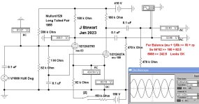
Questions related to the balance of long tailed pairs comes up frequently on DIY.
Here is a simulation based on the 1956 Mullard version where the triodes have mu's of 83 & 100.
The result looks to be more than passable. The key relation is given in red type,
something anyone with a 4-function calculator (or pencil & paper??) can do
in their spare time. For any tail & tubes of this popular circuit. 😀
Attachments
If the tubes in a LTP are mismatched, then the DC balance will be out. Since both grids have the same dc voltage, and both cathodes have the same DC voltage, then the only degree of freedom is the anode voltage. You end up with unequal DC current through each tube (although they will sum to the CCS current) and different DC anode voltages. The CCS forces equal but inverted AC current and anode voltages (assuming matched anode resistors) but distortion may be worse because each tube will be operating on a different part of the curves, and one tube will run out of current or voltage swing earlier than expected, leading to grid current flow.
I like this thread https://www.diyaudio.com/community/threads/balance-in-ccs-long-tailed-pairs.160312/
Not saying that one must use mismatched tubes, but it shows Kirchoff's law.
Not saying that one must use mismatched tubes, but it shows Kirchoff's law.
In the case of mismatched tubes (triodes) the internal plate resistance Rp can be different, regardless of the equal anode current. This Rp is parallel with the external anode resistor for AC, and this could cause AC imbalance. Kirchoff's law applies here too.
With a perfect CCS the LTP is also a perfect current source, so perfectly balanced into equal external loads, for all output that's even order (fundamental 0th order plus even harmonics 2nd, 4th, etc.) but not necessarily for odd order. I think.
I think this is true, but need to wait for MarcelvdG's corrections before really believing it.
All good fortune,
Chris
I think this is true, but need to wait for MarcelvdG's corrections before really believing it.
All good fortune,
Chris
- Home
- Amplifiers
- Tubes / Valves
- How well do LTP driver tubes using CCS need to be matched?