REW has a Calibrate function to set the output levels of the signal generator. It just matches the numbers in REW to the actual output levels.
What are you trying to do with the square wave?
What are you trying to do with the square wave?
It is like that with my Solo as well. So, for square wave tests only external generator.I tried generating a square wave in REW and using the scope to look at the wave. It's 5KHz 192KHz sample rate 250mV, FR Solo. Is this normal?

Tube amp feedback tuning.What are you trying to do with the square wave?
Hi-fi tube amps with feedback typically benefit from assessment of output transformer resonances out past 96kHz. A squarewave used to indicate those resonances has to have a frequency response similarly out past 96kHz. A 192kHz sampling soundcard can't generate or interpret frequencies out past 96kHz, and may well have significant roll-off out past 60-70kHz.
A sig gen and scope with frequency response out beyond 1MHz are a better choice, and can allow single spot frequency measurements out past 90kHz that can identify important magnitude and phase characteristics (like max and min and plateaus of dips and bumps, and zero crossing levels) that work well with an advanced awareness of how close an amp is getting to instability and what changes are of benefit to improve gain and phase margins.
Similarly at low frequencies, a soundcard has falling response that can make assessment of feedback stability impractical, so again it is back to a sig gen and scope to garner that awareness.
Thankfully I have my trusty HP339A, a couple of other HP and Racal generators several Tek 475/465 scopes (I really should update these someday.) and some other gear I haven't used in years. It's fun playing with REW as it does so much very quickly, but as you mentioned, it has it's limitations.
Thanks for your comments.
Cheers
Thanks for your comments.
Cheers
D
Deleted member 148505
SMSL DO100 vs Motu Ultralite MK5 DAC 4.26Vrms and 1Vrms (custom buffer / interface in between)
on Motu UL MK5 ADC
Motu UL MK5 DAC @4.26Vrms

SMSL DO100 DAC @4.26Vrms

Motu UL MK5 DAC @1Vrms

SMSL DO100 DAC @1Vrms

on Motu UL MK5 ADC
Motu UL MK5 DAC @4.26Vrms
SMSL DO100 DAC @4.26Vrms
Motu UL MK5 DAC @1Vrms
SMSL DO100 DAC @1Vrms
Last edited by a moderator:
Thanks for this thread, helped me get started with measuring my progress on an old Marantz I'm restoring. I am hoping to get a little "best practices" type advice generally around measurement repeatability/reducing environmental variables. For instance, I noticed with this Marantz hooked up to a Focusrite 2i2 with a TRS-RCA cable (per RANE 10b, tip to RCA center and sleeve to RCA barrel), regardless of 2i2 output knob position I was audibly picking up a couple AM radio stations when Marantz volume knob was maxed out. With an M-Track Solo (RCA outputs) this didn't happen. With a TS-RCA cable on the 2i2, it seems to have been at least partially mitigated.
In any case, things like AM radio being picked up by the amp inputs doesn't instill confidence that I'm going to have repeatable results hour-to-hour or day-to-day. Some maybe some of the questions I have are:


In any case, things like AM radio being picked up by the amp inputs doesn't instill confidence that I'm going to have repeatable results hour-to-hour or day-to-day. Some maybe some of the questions I have are:
- Best cable setup to use for class-2 non-earth-grounded devices with RCA inputs when the 2i2 is generating the test signals? (desktop PC with earth-grounded USB)
- 2i2 output vs input levels, especially when measuring low output levels from the DUT (e.g. -48dBu)? Seems like 3-oclock on output knob and then adjusting input to get good input resolution is working well to reduce noise.
- Should I use low-pass and high-pass filters for distortion measurements, especially if running 2i2 at 192kHz? (e.g. 10Hz and 22kHz).
- Cable/shielding setup for the 2i2 input to get from speaker terminals, through voltage divider, into the 1/4" TRS or XLR on the 2i2 input? Proximity of my breadboard voltage divider to other electronics (e.g. computer monitors) makes an instantly noticeable difference on the RTA plot.
- RTA settings? Currently using the settings shown below.
Last edited:
Nice work. Try connecting pin 1 (GND) to pin 3 (-ve) on your balanced input breakout cable and see if the noise improves.
I am not sure how the amp can be an AM radio receiver unless it has a built in radio tuner? is there leakage in the mode selector switch?
I am not sure how the amp can be an AM radio receiver unless it has a built in radio tuner? is there leakage in the mode selector switch?
Sorry, I should have been more specific- it’s a 2220B integrated amp/receiver. It does not seem to be AM leakage in the mode switch, moving the tuner doesn’t change anything, seems to be getting picked up in the RCA cables (I’ve heard this is relatively common in guitar amps for instance).
Will give the pin 1-3 connection a try, I will post a few measurements shortly to show where things are at so far (I don’t think they’re bad, just want to make sure I’m doing what I can to minimize external factors).
Will give the pin 1-3 connection a try, I will post a few measurements shortly to show where things are at so far (I don’t think they’re bad, just want to make sure I’m doing what I can to minimize external factors).
Your description suggests that the Marantz has a wide bandwidth which may cause issues when it's connected to your test setup.
When I use my Focusrite for testing, I use a PHONO to TRS adapter at the input, to ensure my grounds are all at the same potential.
You could also try a small series resistor with a parallel capacitor at the input of the Marantz (not in the amp, but in the cable where it plugs into the amp) - 100 ohms with a 220pF cap should do, and won't affect your measurements. I know that some of these older amps used to have a wide bandwidth so that wouldn't be helping if that's the case.
It's also important to keep your interconnects as short as possible, to avoid stray capacitance.
With respect to suppressing measurement quirks (eg. from pickup of external signals, and even from your interconnection scheme), it can be worthwhile noting a few aspects:
- use a large metal tray (or similar metal screen) with the 2i2 and divider and load and as much cabling in the tray, and with any external device like the amp being tested placed nearby, such that cable runs are as short as possible, and screened where possible by the metal tray. The tray may benefit by being linked to the 2i2 ground, or cable screen. Another tray over the top can also help - I use large 'BBQ' trays of aluminium.
- Turn off all nearby lights and equipment to see what affect they may have - I certainly have a noisy LED lamp.
- the 2i2 forms a gnd loop that goes to the amp input and the amp output - if the amp has a long and noisy internal link between its input and output sockets than that noise enters your measurement. Check with a DMM that the 2i2 has its gnds linked between inputs and outputs. You may benefit from not connecting the 2i2 input gnd at say the load divider, or alternatively at the amp input,
- use a laptop to connect to the 2i2 to avoid mains powered earth loops and noise.
FYI... those cheap Ebay load resistors are extremely inductive they will wreak havoc with your THD measurements especially at high frequency. Please see the attached image for the ideal setupThanks for this thread, helped me get started with measuring my progress on an old Marantz I'm restoring. I am hoping to get a little "best practices" type advice generally around measurement repeatability/reducing environmental variables. For instance, I noticed with this Marantz hooked up to a Focusrite 2i2 with a TRS-RCA cable (per RANE 10b, tip to RCA center and sleeve to RCA barrel), regardless of 2i2 output knob position I was audibly picking up a couple AM radio stations when Marantz volume knob was maxed out. With an M-Track Solo (RCA outputs) this didn't happen. With a TS-RCA cable on the 2i2, it seems to have been at least partially mitigated.
In any case, things like AM radio being picked up by the amp inputs doesn't instill confidence that I'm going to have repeatable results hour-to-hour or day-to-day. Some maybe some of the questions I have are:
Here's a photo of my test setup, at the moment I'm use a TS-RCA adapter on each output since it seems to have been the most effective at rejecting the AM radio interference (though not rigorously tested!). Speaker negative terminal connected to XLR pin 3, 2.2k/22k voltage divider to XLR pin 2, XLR pin 1 not connected to breadboard.
- Best cable setup to use for class-2 non-earth-grounded devices with RCA inputs when the 2i2 is generating the test signals? (desktop PC with earth-grounded USB)
- 2i2 output vs input levels, especially when measuring low output levels from the DUT (e.g. -48dBu)? Seems like 3-oclock on output knob and then adjusting input to get good input resolution is working well to reduce noise.
- Should I use low-pass and high-pass filters for distortion measurements, especially if running 2i2 at 192kHz? (e.g. 10Hz and 22kHz).
- Cable/shielding setup for the 2i2 input to get from speaker terminals, through voltage divider, into the 1/4" TRS or XLR on the 2i2 input? Proximity of my breadboard voltage divider to other electronics (e.g. computer monitors) makes an instantly noticeable difference on the RTA plot.
- RTA settings? Currently using the settings shown below.
View attachment 1163379
View attachment 1163392
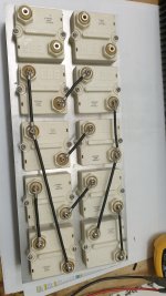
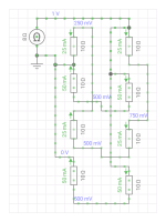
These are 10 ohm resistor wired up a few in series and parallel to achieve 8 ohms.
https://www.ebay.com.au/itm/2541988...kHVuHCkQuC&var=&widget_ver=artemis&media=COPY
Attachments
REW does a good job of measuring the impedance of test loads over the measurement frequency span and should be able to confirm what frequency span is allowable for a test load resistance. There are many ways to prepare a test load, and even compensate for inductive phase shift (I've done that for a few test loads including a precision manganin decade box) - I recall a thread here on compensating the ubiquitous white ceramic 10W WW resistors.
Good idea with metal trays - use alligator clip to ground the tray.
Nice idea on series and parallel to achieve 8ohms from 10ohms. Those are the best load resistors. Basically zero inductance and very linear behavior and can take massive power if heatsinked.
Nice idea on series and parallel to achieve 8ohms from 10ohms. Those are the best load resistors. Basically zero inductance and very linear behavior and can take massive power if heatsinked.
You'd be surprised.I am not sure how the amp can be an AM radio receiver unless it has a built in radio tuner? is there leakage in the mode selector switch?
I as once making an input interface for my Korg DW-8000 synth - something really simple as you can imagine. Said input interface started capturing a Mastercard radio ad...
Ahh, I see. I usually have a 1k series and 220pF film cap to ground on the audio input stage to my amps. This usually filters out most RF radio signals.
Those resistors are available in even higher wattage ratings of 600 watts each at 16 ohm. A little pricey, but I will never have issues with burning one up.

I attach mine to finned CPU coolers with a fan and they can take heat like no one’s business. The 16ohms in parallel gives a 1200w 8ohm dummy load.
I got tired of having a box of test loads so I pulled myself together and made myself a simple "Load Cube" that takes care of essential all my needs: power supplies and power amps as well as line-level projects. Resistance set using one (or more) external "jumpers". Easy interface with measurement equipment. Shielded.
Non-inductive Caddock MP930 (1%, 30W) for power-amp testing (2-16R range in 2R steps). Switch for parallel 100nF to test for stability with capacitive loads.
Dale RH-508 (1%, 50W) for power supply testing (8-64R range in 8R steps).
Symmetrical load for balanced and SE line level sources. Caddock MP930/915 resistors, Greyhill rotary switch (2 deck). 0R3 to 100k range.
- Home
- Design & Build
- Software Tools
- How to - Distortion Measurements with REW