Do you recall modifying the termination points of the wires coming from the rectifier, and the starring of 0V wires to the amp modules and speakers - that are shown in the wiring diagram as going to the mid-point of the capacitor bank 0V bus, and to just the middle capacitor terminal posts? Imho, changing those termination points would mainly account for the before/after spectrum plots, and the insertion of 0.1 ohm resistors would be more the icing on the cake.
Agree with the ground wires not optimum.
The connection of ground from rectifiers to copper ground plane should stay as-is.
The ground from PS to right board should connect to the end of the right side of the copper ground plane. The ground from PS to left board should connect to the end of the left side of the copper ground plane. This places the amplifier ground at the power supply filter outputs instead of the power supply filter input, where the ground is "dirty". The positive, negative, and ground wires for each channel should be twisted together to minimize loop area.
The speaker grounds wires should connect to the ground at their respective channel boards, and twisted with their respective speaker signal out wires to their output jacks. That would minimize loop areas.

Agree regarding grounding!
I also want to add that two extra 0.1 ohm resistors could be placed directly after the rectifying bridge. RCRC... No there will be no "dynamic loss", maybe less distortion that could be sujectively interpretated as dynamic loss.
I actually put in some lossy toroidal chokes of 160uH and 0.1ohm before the first capacitor. the 0.1ohm resistor is damping hf ringing.
IF you or anyone considering to add "fast" polyprop caps you shall place them as close as possible to the power stage!! Never close to the rectifier. 1. They are useless at that position due to inductance in al wiring between power supply and power stage.
2. They are creating EMI spikes from the rectifier...
esl 63, I would suggest there is a place for a tuned CRC snubber directly across a power transformer secondary winding, as it acts directly on the leakage inductance in the secondary winding that is imho the root cause of diode commutation noise generation. Placing additional parts in series with the diodes, or in parallel to them, is in my view a worrying complication.
If you are extremely talented you can avoid the extravagant and unnecessary expense of USD 0.50 , by using an RC snubber rather than a CRC snubber -- but this requires EXPERT operation of oscilloscope probes in the presence of lethal mains voltages. In most cases it's safer and better to guard your life and your haploid cells by using a 9V battery powered test jig instead of live probing with actual mains attached. Or that's my opinion, anyway.
Mark, the MX50 SE appears to typically use a power transformer secondary voltage of say 24Vac. Are you saying there is a mains AC hazard with testing snubbers on the secondary side?
Yes! A snubber is very effective, reference to the thread Quasimodo in this forum. Highly recommended!
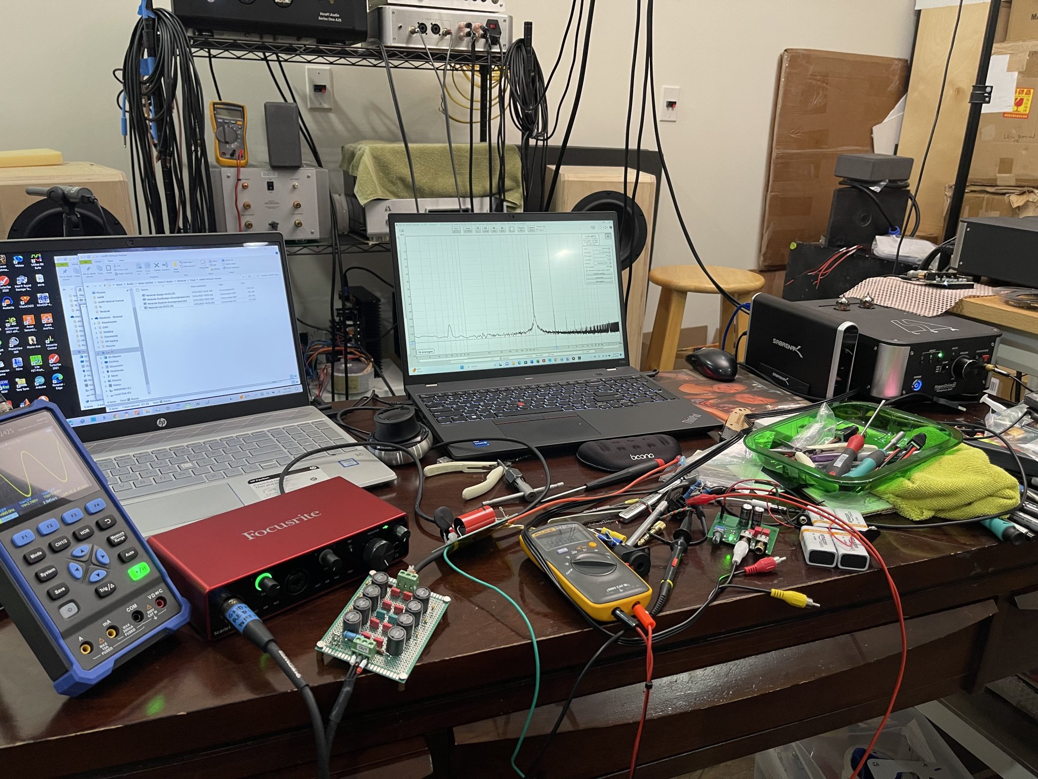
I just tested a hybrid headphone amp with a TPA6120A2 output buffer and E88CC tube buffer stage and used my trusty REW setup with a Focusrite 4i4 3rd gen audio interface, Victor’s 1kHz oscillator, and my usual balanced input signal divider rig. The headphone amp measures nicely and I was pleasantly surprised to find that 293mW into 33ohms produced a rather pleasing harmonic profile. The background noise with inputs shorted also showed a great low baseline noise level.
Here’s the setup:
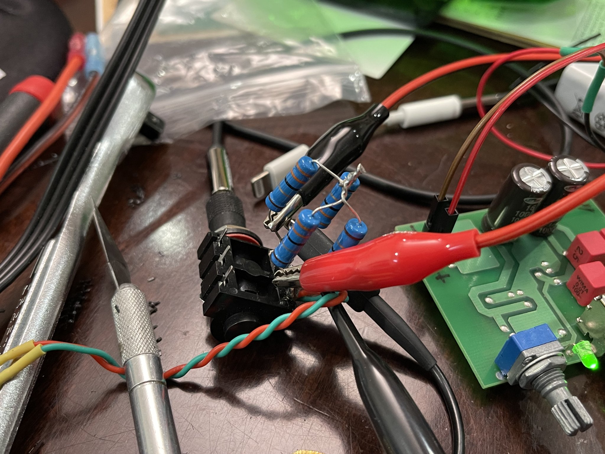
This is the 33ohm dummy load made from 4 series-parallel 33ohm 2W metal thin film resistors:
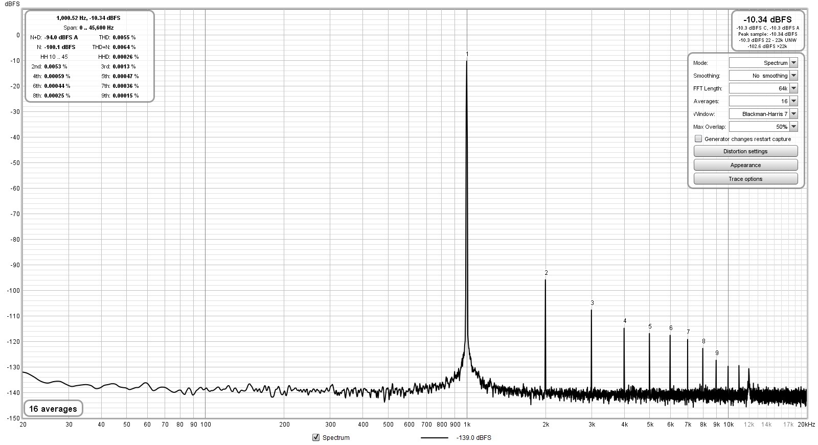
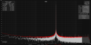
Here is 293mW into 33ohms:
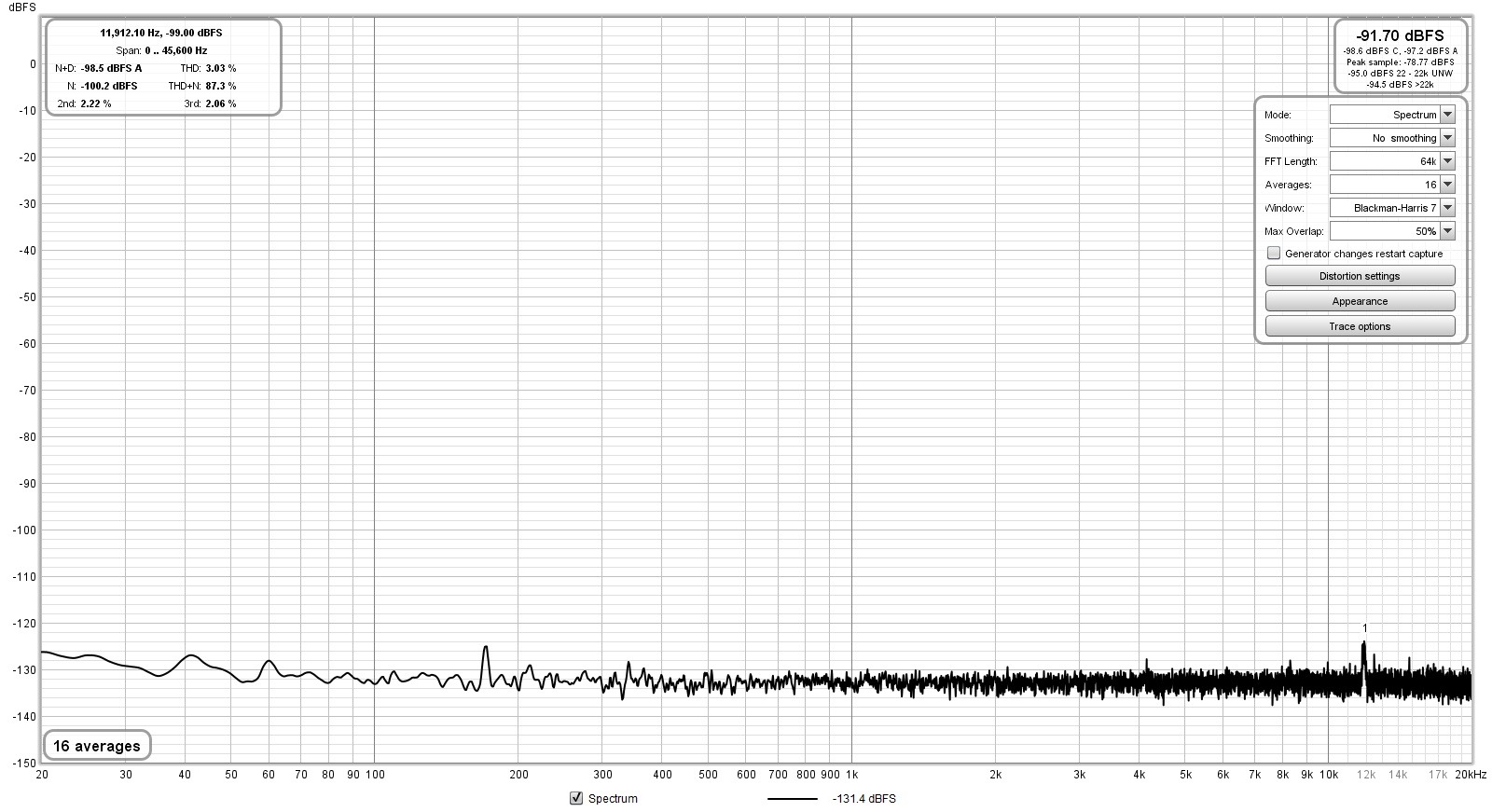
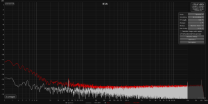
Background noise with inputs shorted. -10dB is 1.0Vrms for reference:
Here’s the setup:
This is the 33ohm dummy load made from 4 series-parallel 33ohm 2W metal thin film resistors:
Here is 293mW into 33ohms:
Background noise with inputs shorted. -10dB is 1.0Vrms for reference:
It’s really cool to be able to test the audio equipment you own. It took me some time to build the cables to connect my Focusrite Scarlett solo 3rd gen and the dummy load, but testing was easy and fun.
I have an old DAC with a headphone amp that I bought like 10 years ago, Matrix Cube. I tested the headphone amp and I think it measures OK.

My old Yamaha RX-V650 in pure direct mode measures below specs for 1W into 8 ohms.

I’m a little disappointed by an amp that I build myself using Kaltecs Ultra-Low Distortion 100W Amplifier Kit based on TDA7293 with Low-Noise PSU. It does not measure better than my old Yamaha.

All measurements -10dB, 1.0Vrms
Background noise with no input for reference.

I have an old DAC with a headphone amp that I bought like 10 years ago, Matrix Cube. I tested the headphone amp and I think it measures OK.
My old Yamaha RX-V650 in pure direct mode measures below specs for 1W into 8 ohms.
I’m a little disappointed by an amp that I build myself using Kaltecs Ultra-Low Distortion 100W Amplifier Kit based on TDA7293 with Low-Noise PSU. It does not measure better than my old Yamaha.
All measurements -10dB, 1.0Vrms
Background noise with no input for reference.
What's the harmonic profile of this oscillator? Is it better than what the Focusrite would output driven by REW? How much additional distortion does the little headphone amp put on top of its input harmonic profile?Victor’s 1kHz oscillator,
I assume anything makes something, then anything chained after adds to it, either on top of or by introducing something new.
It’s so low that you can’t see what its harmonic profile is. That is, what you measure is the loop back of the ADC harmonic profile. Maybe someone has used a high gain low distortion and low noise amp to measure the oscillator?
It’s below -150dB harmonic distortion at 1kHz.
https://www.diyaudio.com/community/...ion-measurements-with-rew.338511/post-6969353
It’s below -150dB harmonic distortion at 1kHz.
https://www.diyaudio.com/community/...ion-measurements-with-rew.338511/post-6969353
Yes it's low.
I could measure around -143dB THD with my rig... I know that the Cosmos ADC with the APU notch I also use can reach near -150dB on the same setup.
https://www.diyaudio.com/community/threads/behringer-umc-202hd-for-measurements.341309/post-7317942
Jesper.
I could measure around -143dB THD with my rig... I know that the Cosmos ADC with the APU notch I also use can reach near -150dB on the same setup.
https://www.diyaudio.com/community/threads/behringer-umc-202hd-for-measurements.341309/post-7317942
Jesper.
It is possible the create a ground loop generating a lot of noise when using Focusrite only? Using an USB DAC for output and Focusrite for input the measurements of my diy amp are much improved. I wonder if this is a common problem.

hi - some rough measurements (Cosmos ACD + Victor osc.; cosmos is set for 2.7V sensitivity, Victor's output is 2.2V; RCA to xlr cable, no mono mode)What's the harmonic profile of this oscillator? Is it better than what the Focusrite would output driven by REW? How much additional distortion does the little headphone amp put on top of its input harmonic profile?
I assume anything makes something, then anything chained after adds to it, either on top of or by introducing something new.
i get different noise measurements depending option i chosen. If "manual fundamental" option is clicked then noise is ~128dBfs, if not -> ~110dBfs
Attachments

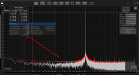
Hard to see in above graphs but it seems the fundamental is at -15dB, so the 2nd really isn't much more than 130dB down.
I've measured Viktor's oscillators at -150 below fundamental so it seems the above measurement is test equipment limited and doesn't show what Viktors stuff can do.
It is anyway always a good idea to set the 0dB ref to the fundamental to avoid confusion.
Remember, dB values are always relative, never absolute.
Jan
Using the mic input of the soundcard for measurements is no good idea at all. Besides ultra-low noise at high gain - useful for real-life mic amplification - noise and distortion figures at minimum gain never reach the level of a good line-in. A simple loopback measurement will prove that. So I urgently recommend to use line-in instead of mic-in.
Concerning the dB discussion here: I prefer a dBFS scaling, this makes it easy to measure around the sweet spot of the soundcard. Which often is several dB below FS. Next step is set distortion display to dB instead of % - much easier to compare than counting the zeros.
Concerning the dB discussion here: I prefer a dBFS scaling, this makes it easy to measure around the sweet spot of the soundcard. Which often is several dB below FS. Next step is set distortion display to dB instead of % - much easier to compare than counting the zeros.
Last edited:
I'm glad to read and see such excellent performing equipment is available for those working on Ultra Low distortion amplification. For more regular folks, who might build a tube amp or other audio flavoring circuits, I'm still curious how the ordinary analog out of the Focusrite DAC compares, when driven by the sine signal REW generates.
It must be a concern for the ULD designers, as it's a pain to unwrap your distortion from someone else's upstream distortion, with confidence to be able to report it. I understand that's why Victor's oscillator's performance is valuable.
It must be a concern for the ULD designers, as it's a pain to unwrap your distortion from someone else's upstream distortion, with confidence to be able to report it. I understand that's why Victor's oscillator's performance is valuable.
- Home
- Design & Build
- Software Tools
- How to - Distortion Measurements with REW