Panelhead,
Thanks for showing us all the measurements. Please set your plot scale at 10dB per division and range from 0dB to -140dB. It’s hard to see the detail on 50dB to -250dB range when so signal is only a fraction of that. When you do that maybe your distortion window will show % vs dB which is harder to compare to numbers we know.
Thanks,
X
As for the 100hz, that is what I don't understand. If the frequency response is flat to 20hz, how can 100hz be attenuated? I thought seeing poor square waves on the low frequency indicated a rolloff. How can you have poor square wave performance *and* a flat FR?
And are you saying that the interface is AC coupled, and the cap isn't large enough for a low enough rolloff?
If you think about what makes a 10 Hz square wave appear square, that is, having not only a steep rise (harmonics at multiples of the fundamental), but also what makes the top appear flat ... 😛
You can think of a square wave as superposition of lots of sine waves at different frequencies (multiples), but for the top to appear flat, you need the sub-harmonics of the fundamental 😀.
That is why all low-frequency square waves have a sloping top when the amp does not have constant amplitude gain right down to DC 😉
Best regards, Claas
Thanks Class! I didn't realize that the harmonics were below as well as above the fundamental!
If you think about what makes a 10 Hz square wave appear square, that is, having not only a steep rise (harmonics at multiples of the fundamental), but also what makes the top appear flat ... 😛
You can think of a square wave as superposition of lots of sine waves at different frequencies (multiples), but for the top to appear flat, you need the sub-harmonics of the fundamental 😀.
That is why all low-frequency square waves have a sloping top when the amp does not have constant amplitude gain right down to DC 😉
Best regards, Claas
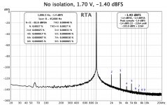
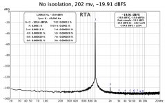
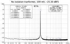
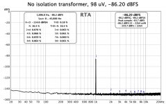
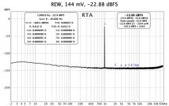
Reran the RTA plots
The scaling may be easier to read, and it shows THD as a percent.
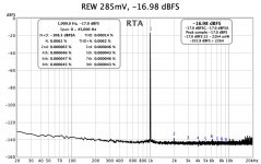
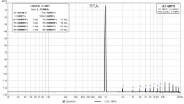
The Akitka does not have the range of output in my system. Minimum is above -90.3 dB, and wide open is not 0 dB. Plus wide open the plot shows some harmonics of the 1khz signal. The REW does not show this, just a higher noise floor.
The scaling may be easier to read, and it shows THD as a percent.
The Akitka does not have the range of output in my system. Minimum is above -90.3 dB, and wide open is not 0 dB. Plus wide open the plot shows some harmonics of the 1khz signal. The REW does not show this, just a higher noise floor.
Attachments
The scaling may be easier to read, and it shows THD as a percent.
The Akitka does not have the range of output in my system. Minimum is above -90.3 dB, and wide open is not 0 dB. Plus wide open the plot shows some harmonics of the 1khz signal. The REW does not show this, just a higher noise floor.
What is the load impedance? Are the voltages shown Vpp or Vrms? And voltages input or at the load?
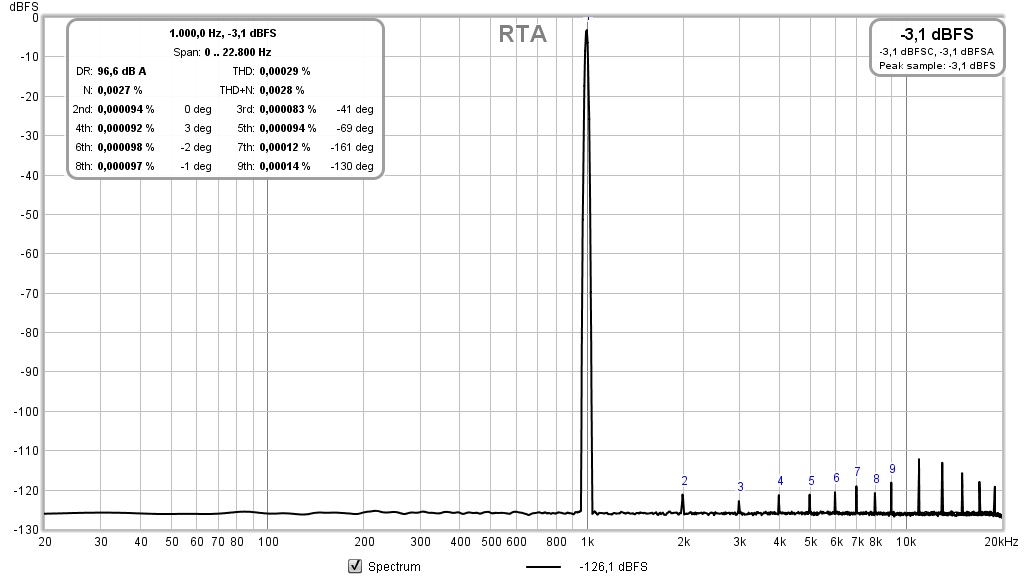
These were loopback tests using the Clarett. The voltage is RMS.
The Akitika 2ppm generator is plugged into one pair of line inputs, the looped back line output into another.
These loopback tests were just to see where REW and the Clarett 4Pre ended up as far as resolution and noise. The DUT’s are low noise amplifiers.
Still sorting out REW and the capability. The computer is a late 2012 Mac Mini. There have been several upgrades implemented in the audio cards.
From the AP tests the REW and Clarett are right about where the amplifiers measure. This is a noise floor at -140 - 145 dB. Would love to see the RTA noise floor down another 5 - 10 dB.
No subharmonics in a square wave.If you think about what makes a 10 Hz square wave appear square, that is, having not only a steep rise (harmonics at multiples of the fundamental), but also what makes the top appear flat ... 😛
You can think of a square wave as superposition of lots of sine waves at different frequencies (multiples), but for the top to appear flat, you need the sub-harmonics of the fundamental 😀.
The slope is due to phase/group delay changes near to the pole of the high-pass (subsonics) filter.That is why all low-frequency square waves have a sloping top when the amp does not have constant amplitude gain right down to DC 😉
Best regards, Claas
Mark, of course you're right.
Here is an article (by Rod Elliott) that explains it quite well and in an understandable fashion:
Squarewave Testing
Regards,
Claas
Here is an article (by Rod Elliott) that explains it quite well and in an understandable fashion:
Squarewave Testing
Regards,
Claas
Is it possible to use the REW and Behringer sound card to test a balanced output preamp? Wiring and XLR to Stereo 1/4" phono plug for connection between Behringer and preamp output?
OK, I think I would use the balanced + for the tip of the TRS and the balanced - for the TRS ring and ignore the balanced ground. The REW display would show the combination + & - and adjusting H2 on each side would show up as the combined?
Use it that with an input transformer
When connecting single ended and balanced components I generally use a TS connector for the 1/4” plug.
Installed an input transformer in a single ended amplifier and connect Ring and Tip to it. The sleeve connects to chassis. The grounding gets complicated sometimes when changing from SE to balanced.
All the pro gear I have used worked fine with a TS plug in a TRS jack.
Except that in a TS jack, the ring (-ve) is now shorted to ground and that may cause the source to have distortion since it is driving a 0ohm load (unless it has internal series 600ohm resistor).
Is this 16 or 24 bit signal?
I assume you are using the REW signal generator. Is it set as 16 or 24 bit?
This is what I could achieve with a modest Sound Blaster Audigy SE.
Great thread, xrk971 !!!
I will start playing a little with the amplifiers that I have.
I assume you are using the REW signal generator. Is it set as 16 or 24 bit?
I assume you are using the REW signal generator. Is it set as 16 or 24 bit?
16 bit. Internal signal generator.
- Home
- Design & Build
- Software Tools
- How to - Distortion Measurements with REW