Can you run 24 bit?
The 24 bit signal should drop the noise baseline even lower.16 bit. Internal signal generator.
The 24 bit signal should drop the noise baseline even lower.
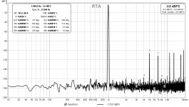
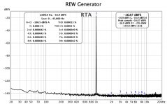
Now, with 24 bit internal REW signal generator 🙂eek🙂:
Attachments
Last edited:
Now that is impressive. Try a signal level around -20 dB. That should drop the harmonics.
If this is a true loopback you are ready to measure any amplifier made.
If this is a true loopback you are ready to measure any amplifier made.
Nice work Diegomj!
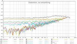
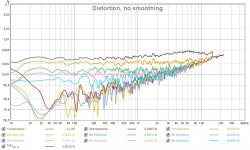
That soundblaster Audigy sound card appears to be quite good. It’s a bit different than the Focusrite on harmonic profile. Although very low THD, has a higher 5th order. What amp do you have in mind to measure? I recall measuring your DLH as a function of “sweetness” knob. That was an interesting exercise.
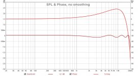
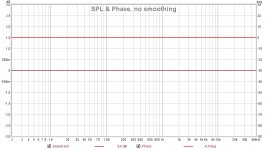
One thing that concerns me is the SPL and phase plot. Looks like there is a brick wall filter at 20kHz and that is causing huge phase shifts past 10kHz. You might try setting the acquisition to 96kHz and collect at least to 30kHz. Phase on a good amp should be flat within 5 degrees up to about 200kHz to 300kHz for the best sound stage and imaging.
Cheers,
X
That soundblaster Audigy sound card appears to be quite good. It’s a bit different than the Focusrite on harmonic profile. Although very low THD, has a higher 5th order. What amp do you have in mind to measure? I recall measuring your DLH as a function of “sweetness” knob. That was an interesting exercise.
One thing that concerns me is the SPL and phase plot. Looks like there is a brick wall filter at 20kHz and that is causing huge phase shifts past 10kHz. You might try setting the acquisition to 96kHz and collect at least to 30kHz. Phase on a good amp should be flat within 5 degrees up to about 200kHz to 300kHz for the best sound stage and imaging.
Cheers,
X
Last edited:
Now that is impressive. Try a signal level around -20 dB. That should drop the harmonics.
If this is a true loopback you are ready to measure any amplifier made.
Honestly, I'm surprised given the low cost of that sound card.
I am going to test what you have suggested to me, that is, decrease the intensity at -20 dBFS of the fundamental signal of the internal generator of the REW.
Best regards
Nice work Diegomj!
That soundblaster Audigy sound card appears to be quite good. It’s a bit different than the Focusrite on harmonic profile. Although very low THD, has a higher 5th order. What amp do you have in mind to measure? I recall measuring your DLH as a function of “sweetness” knob. That was an interesting exercise.
One thing that concerns me is the SPL and phase plot. Looks like there is a brick wall filter at 20kHz and that is causing huge phase shifts past 10kHz. You might try setting the acquisition to 96kHz and collect at least to 30kHz. Phase on a good amp should be flat within 5 degrees up to about 200kHz to 300kHz for the best sound stage and imaging.
Cheers,
X
Although the parameters are more than interesting, I do not really like what my sound card does over the H9.
Anyway, I want to start playing with the idea of Eduardo de Lima (that is, trying to minimize the acoustic distortion of a full-range speaker, which is what finally reaches our ears, in the widest range of frequencies that can be). For this, I will try to implement a single-ended amplifier with distortions comparable to those that can be measured from the available speaker. The basis of the operation of the DLH could serve me for this purpose (although I would have to make it distort more grossly, like 2% or more). Actually, for the idea with which I want to play it is interesting to have great cleanliness between the fundamental and the included H3.
Best regards
Last edited:
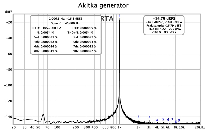
My Sound Blaster Audigy SE at 96K:

Attachments
Last edited:
Very nice. The 96k did the trick because you were hitting a brick wall filter with other one. Those are very good loopback figures but I see what you mean about the higher order harmonics.
I cannot get close to that plot
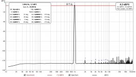
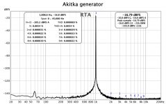
The 24 bit numbers are very hard to believe. That is the lowest noise floor I have seen with the 24 bit pulse. This is 23 - 24 bit, which is 2 bits better than the dCS, Benchmark, and other SOTA dacs.
Blows mine away, I get lower noise with the Akitka generator, and better looking waves with the REW.
I may just need a computer with a better sound card.
Attachments
Panelhead,
Sorry - I am confused. The great measurement you post above, is this yours? If so what sound card was used? You say it is not yours but this appears to be the lowest distortion loopback I have ever seen in REW. That’s 0.69ppm and less than the 2ppm level that the Akitika generator.
Sorry - I am confused. The great measurement you post above, is this yours? If so what sound card was used? You say it is not yours but this appears to be the lowest distortion loopback I have ever seen in REW. That’s 0.69ppm and less than the 2ppm level that the Akitika generator.
My sound card uses X-fi mod drivers. It could be those drivers that make the differences that are shown. I have seen very positive changes compared to the original Sound Blaster drivers, in extensive listening sessions.
I'm not optimistic about the noise floor I get with the internal generator operating at 24 bits. It would be more realistic to expect a noise floor at no more than 144 dB from the fundamental.
I would be satisfied with obtaining a noise floor at 100 dB below the fundamental, like original soundcard specs.
Last edited:
Sorry to be confusing
I want it all. I see the -170 -175 dBFS noise baseline from the Sound Blaster. I have spent a little time trying to get better.
This is the third set of cables from the Akitika to the Clarett 4Pre. Started with a set of gimme RCA and changed one end to a TS plug. Then found I had a short pair of RCA to TS microphone cables. Finally made a set of coaxial with crimp on RCA and TS. The first set was picking up noise and moving it around changed the plots by 10 dB or more. These Canare LS-5 seem immune to noise. Using a pair of Canare Star Quad as loopback cables too. About a foot long.
When looking at levels this low cables can make a difference.
My late 2012 Mac Mini is seven years old. The integrated sound card is low end.
I think a higher spec sound card might improve the loopback.
Panelhead,
Sorry - I am confused. The great measurement you post above, is this yours? If so what sound card was used? You say it is not yours but this appears to be the lowest distortion loopback I have ever seen in REW. That’s 0.69ppm and less than the 2ppm level that the Akitika generator.

I want it all. I see the -170 -175 dBFS noise baseline from the Sound Blaster. I have spent a little time trying to get better.
This is the third set of cables from the Akitika to the Clarett 4Pre. Started with a set of gimme RCA and changed one end to a TS plug. Then found I had a short pair of RCA to TS microphone cables. Finally made a set of coaxial with crimp on RCA and TS. The first set was picking up noise and moving it around changed the plots by 10 dB or more. These Canare LS-5 seem immune to noise. Using a pair of Canare Star Quad as loopback cables too. About a foot long.
When looking at levels this low cables can make a difference.
My late 2012 Mac Mini is seven years old. The integrated sound card is low end.
I think a higher spec sound card might improve the loopback.
No the loopback function of the Clarett 4Pre is fixed. It uses outputs 1&2 routed to line inputs 5&6. It uses a FGPA for routing. I am using 1’ Canare Star Quad cables and Amphenol T series TRS plugs for the loopback cables.
Feeding the Akitika into line inputs 7&8. Using about 2’ of Canare CFB-5 coax to connect the Akitika and Clarett.
I see the 1Khz signal from the Akitika is going through the ADC twice.The analog output into 7&8. Then the digitized signal feeding the DAC. And then the analog output of the Dac chip back into line inputs 5&6 to the ADC. The digitized signal is then transferred back to the computer.
I think this is why I see the frequency spread on the sine wave. The spread is level dependent also, cranking up the signal level widens the spread.
Wow, that’s confusing. I am not even sure what you are trying to achieve with the tortuous multiple loopbacks? Why not let the Akitika go direct to the input?
"Then the digitized signal feeding the DAC. And then the analog output of the Dac chip back into line inputs 5&6 to the ADC." This part doesn't make sense. Are you routing the input to dac internally and then went back into the adc again? I think you may be just routed the output to the internal input digitally. Hence this low distortion. There is no way the input of clarett has this low distortion. Clarett has minimum of 0.00005% at around -20dbFS.No the loopback function of the Clarett 4Pre is fixed. It uses outputs 1&2 routed to line inputs 5&6. It uses a FGPA for routing. I am using 1’ Canare Star Quad cables and Amphenol T series TRS plugs for the loopback cables.
Feeding the Akitika into line inputs 7&8. Using about 2’ of Canare CFB-5 coax to connect the Akitika and Clarett.
I see the 1Khz signal from the Akitika is going through the ADC twice.The analog output into 7&8. Then the digitized signal feeding the DAC. And then the analog output of the Dac chip back into line inputs 5&6 to the ADC. The digitized signal is then transferred back to the computer.
I think this is why I see the frequency spread on the sine wave. The spread is level dependent also, cranking up the signal level widens the spread.
I will check this. If just the Akitka in I should be able to unplug the loopback cable and get the same plot.
Leaving for a few days, will check when back.
Leaving for a few days, will check when back.
I will check this. If just the Akitka in I should be able to unplug the loopback cable and get the same plot.
Leaving for a few days, will check when back.
Or maybe it's possible. Your level seems to be pretty low. But in that case you can directly plug it in the line input.
Also your graph "looks" amazing but actually you can use higher fft length and see deeper in the noise floor. I remember did loop test around that level and achieve 0.00008% thd and 0.00006% with a different source.
Glad I found this thread, I'm just about to build a new dual mono preamp so this is great info. I put buying that 8903A and 8561A on hold and bought a Focusrite solo.
Glad I found this thread, I'm just about to build a new dual mono preamp so this is great info. I put buying that 8903A and 8561A on hold and bought a Focusrite solo.
Don't worry too much. Actually you can use rew's ore distortion feature to calibrate the system for very low thd and then measure. Just only need to make sure it's not at clipping. Generally it's very accurate.
- Home
- Design & Build
- Software Tools
- How to - Distortion Measurements with REW