Yes. The SSR’s actually reduces the measured distortion at higher powers. The design by Jhofland is excellent. More info in this thread.
Great, thank you. I think a SSR is my next project.
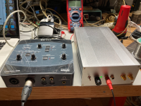
I am just getting back to messing around with REW using my old EMU 0404 USB. I got one of Victors oscillators (latest version) and put it in an aluminum box. Power comes from 4 Lithium 9volt batteries (actually about 8.4 volts each). So far I have only tried a quick and dirty REW run with the oscillator directly feeding the EMU, but the results look promising.
The EMU was running off a 5 volt USB battery pack and my Macbook was running on battery as well. The version of REW is the latest for MacOS.
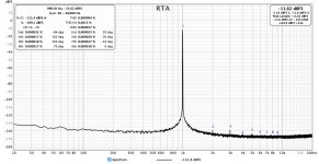
With the oscillator output at -11.6 dB (about .5volts RMS) feeding the XLR input (with one side grounded), I am seeing 0.000084% THD and 0.0013 THD+N. The noise is a function of the EMU A/D paths and would require some mods to get it lower (and some shielding inside the box).
This is definitely an improvement over using the EMU to output a sine wave, so I can recommend Victors oscillator to anyone trying to get a pure signal.
The EMU was running off a 5 volt USB battery pack and my Macbook was running on battery as well. The version of REW is the latest for MacOS.
With the oscillator output at -11.6 dB (about .5volts RMS) feeding the XLR input (with one side grounded), I am seeing 0.000084% THD and 0.0013 THD+N. The noise is a function of the EMU A/D paths and would require some mods to get it lower (and some shielding inside the box).
This is definitely an improvement over using the EMU to output a sine wave, so I can recommend Victors oscillator to anyone trying to get a pure signal.
Attachments
Have you tried the Emu in loopback with the sinewave preadjusted to suppress measured harmonics?
with the sinewave preadjusted to suppress measured harmonics?
How do you do that?
The Generator 'Tones' button has the Sine button selection which includes an "add harmonic distortion" tick box, which brings up a new selection Distortion Controls box for adding in harmonic levels/phases that can be used to suppress the measured distortion. This can be used not only to suppress the soundcard THD, but also to suppress an external devices THD (eg. by including say an amp in the loopback) - which is great for making your own very low distortion THD test oscillator.
So a fixed/static predistortion. Very interesting. I wonder how stable the cancelled distortion is. How much suppression/cancellation have you achieved?
Cancellation varies if settings are changed, such as sine frequency and amplitude, given harmonics are down in the weeds.
Distortion analysis - a thought experiment
Distortion analysis - a thought experiment
Have you tried the Emu in loopback with the sinewave preadjusted to suppress measured harmonics?
That's an interesting technique. I may give it a go. However, I do like the simple approach of using a sine as pure as possible for the DUT from a separate oscillator. As I mentioned the noise of the EMU A/D swamps distortion at these levels, and I can't think of a way to null the noise out. At this point, maybe a custom A/D converter with modern parts.
I will be trying a notch filter as well as the Bob Cordell technique of injecting a small pilot tone.
Yes it can be fun. Are you assuming the Victor oscillator harmonics are below your EMU noise floor? What REW RTA settings did you use for post #882 ?
Coherent averaging will drop the noise floor to reveal the harmonics.As I mentioned the noise of the EMU A/D swamps distortion at these levels, and I can't think of a way to null the noise out.
D
Deleted member 148505
I have found that wire wound ones in a metal shell for heatsink mount is about same as white cement filled ones or the green wire wound ones. You want metal thin film. Some thin films are metal oxide thin film and those are bad. They will give you 0.02% vs 0.001% for example. Definitely, the big green 100w wire wound is terrible.
The best I have tried are the EBG UXP.
@wtnh, those Caddocks look really nice. Their trade name “Micronox” sounds like it is a metal oxide thin film and not plain metal thin film
I have big green wirewounds 1000W and 100W and I would say that they are decent.
Just make sure that you'll get an exact resistance value because probably the reason that you'll getting inferior THD performance is that they have lower resistance, than the one that you compare it to (like datasheet performance at specific load impedance)
I use 2pcs parallel 8ohms green 100w wirewound for my 4ohms amp measurements. The parallel config has near perfect 4ohms resistance compared to my single 4ohms 100W which measures at 3.8ohms.
Coherent averaging will drop the noise floor to reveal the harmonics.
Well, as they say, RTFM. 🙂
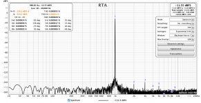
With coherent averaging turned on, THD is now showing 0.000055% (predominantly 2nd and 3rd H) and THD+N is down to 0.00024%! The EMU input LEDs are showing -12dB.
Since this is less than 1 PPM, I'd say I'd be hard-pressed to improve much further with Victors oscillator and the EMU 0404(without mods). Maybe better cables and shielding would help too.
Thanks, John!
This all raises an interesting point. Those of us using REW for distortion measurement (primarily the RTA functions) probably have no two setups configured identically, so it is never an apples-to-apples comparison.
Attachments
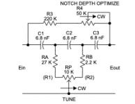
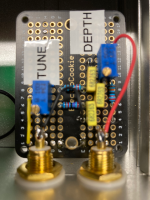
I decided to add a passive notch filter to the box with Victors oscillator. This is a very simple Hall-type network documented in this article by Kenneth Kuhn. The two pots allow it to be tuned to the oscillator and get the best notch depth possible. I am sure the "Q" of this thing is not great, but it will give me a basis for experimenting.
I assembled the filter on a small perf board and mounted it directly on isolated RCA panel jacks. I matched the caps to within about 0.2% by selecting components. The resistors are metal film and the pots are cermet. The notch is completely independent of the oscillator and can be hooked in or not. A preliminary test with REW indicated I could get about -74dB fundamental suppression. Better results could be obtained with an active Hall circuit, but adding active devices would increase THD+Noise. Even the types of capacitors and resistors used can influence distortion.
There is a good website here describing how to use a notch filter for making distortion measurements.
It would be better to build this with BNC connectors, which are typically used for low noise measurement equipment, but I did not have any handy. I may upgrade the whole thing (including Victors board) to BNC at some point.
Attachments
Coherent averaging by principle reduces noise, therefore the noise-related figures in the chart are correctly marked with a different color. IMO they are irrelevant in this mode.
The question is why also the distortions drop in most cases. IMO the reason is their phase fluctuates against the fundamental a bit, reducing thus their vector average magnitude. That is why I wonder if the vector-averaged THD at these tiny fluctuating distortions is relevant.
I have made many measurements with EMU 0404 USB. I am surprised your ADC part is capable of this tiny distortion. My split-side measurements show the harmonics at -10.3dB fundamental seriously higher https://www.diyaudio.com/forums/equ...nsation-measurement-setup-40.html#post6507785. E.g. H2 at -129 - (-10.3) = -118dBr, H3 at about the same. The splitting method has been confirmed to yield correct values by several independent experiments, therefore I trust the distortion magnitudes measured on my ADC side.
I still wonder if the lower frequency stability of an analog oscillator can have some effect on the distortions as measured by REW. John, please may I ask you to shed more light on this? Thanks a lot.
Last edited:
I agree that averaging the noise is a bit artificial. As John mentions, its function is to reveal harmonics that might otherwise be buried in the hash. Perhaps the phase noise of the oscillator is responsible for the THD reduction when using coherent averaging - maybe John can provide insight as to how that might be measured with REW.
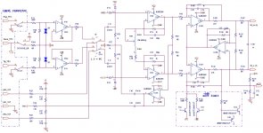
I think one thing that helps when using the EMU is to utilize the XLR inputs. This bypasses the 5532 Hi-Z input buffers. In my test, I grounded one of the balanced input legs on the XLR. It would be preferred to have the oscillator provide balanced outputs in order to take advantage of the CMRR of the differential amplifier in the EMU. It uses Bill Whitlock's very clever differential bootstrap technique to boost the CMRR. The differential opamps are NJM2068s, which, in their day, were not too shabby.
I think one thing that helps when using the EMU is to utilize the XLR inputs. This bypasses the 5532 Hi-Z input buffers. In my test, I grounded one of the balanced input legs on the XLR. It would be preferred to have the oscillator provide balanced outputs in order to take advantage of the CMRR of the differential amplifier in the EMU. It uses Bill Whitlock's very clever differential bootstrap technique to boost the CMRR. The differential opamps are NJM2068s, which, in their day, were not too shabby.
Attachments
I think one thing that helps when using the EMU is to utilize the XLR inputs. This bypasses the 5532 Hi-Z input buffers. In my test, I grounded one of the balanced input legs on the XLR. It would be preferred to have the oscillator provide balanced outputs in order to take advantage of the CMRR of the differential amplifier in the EMU. It uses Bill Whitlock's very clever differential bootstrap technique to boost the CMRR. The differential opamps are NJM2068s, which, in their day, were not too shabby.
I assume the same trick is used on the E-MU 1820/1616? (That would explain the "extra" NJM2068 on the PCB.)
Where did you find the schematics for the E-MU?
What do you think of upgrading the NJM2068 with LM4562, OPA1612 or OPA1642? OPA2228 has low current noise but high price.
Somewhere in the forums here, somebody who was working on modding the EMU 0404 posted a reverse-engineered schematic on the unit (at least the input section). Sorry - I don't recall which entry. If I find it again, I'll post it here.
The EMU 0404 (and other EMU devices) is mostly SMD devices - I am not sure how practical it would be to retrofit opamps, but I am sure you could do it with enough determination. 🙂
There are other mods that can be done to improve the performance, but it might be a case of diminishing returns. In my case, the EMU was sitting on a shelf for many years, so I figured why not use it for amplifier distortion analysis, essentially free to me.
See this post for how I used the balanced XLR inputs to get better results doing amp measurements.
Last edited:
The USB version of EMU0404 had a difference in noise level between channels - that started some forum investigation and modding so as to suppress the internal smps spikes that are evident on the left channel (I noted your photo had used the right channel when you posted that). I haven't modded my 0404 as I use the right channel if ever I need an aesthetically clean response. There are many forum threads you can find by googling 0404 etc.
Do you have a sample spectrum of Victor's oscillator from an AP measurement to compare with the EMU response - as a way to appreciate the influence of the EMU input and ADC stage? That would be helpful as a way to better appreciate how the EMU (and any external amp) can be used to provide a low HD test oscillator by using the REW add HD function.
Do you have a sample spectrum of Victor's oscillator from an AP measurement to compare with the EMU response - as a way to appreciate the influence of the EMU input and ADC stage? That would be helpful as a way to better appreciate how the EMU (and any external amp) can be used to provide a low HD test oscillator by using the REW add HD function.
- Home
- Design & Build
- Software Tools
- How to - Distortion Measurements with REW