It is more likely X measured a contact distortion problem, an effect I can confirm based on my own measurements. As Jan stated, to measure the amp and nothing else it is mandatory to measure before any connectors on the way to the load.XRK971 also discussed earlier in the thread that he had found distortion in power resistors that became a factor when measuring THD for some of his low-distortion amplifier designs, for example #826 and #535.
Regards, Claas
Last edited:
What I meant. Reliably and repeatably measuring very low distortion isn't just slapping a couple of probes on somewhere.
Jan
Jan
Attachments

Last edited:
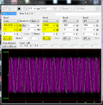
Can I bring up another question. I use REW a lot with shaped burst signals to test amplifiers without overheating them.
This works extremely well and REW is very flexible in setting up the signal parameters.
But such signals make it hard for a scope to trigger on, and what is needed is a sync signal, like the unmodulated signal, on the unused output channel of the soundcard.
Is it possible to send out different signals on the two channels of the soundcard? As far as I can see the REW generator can only output one signal to either or both channels. Is it possible to spawn another generator instance that sends another signal to a channel output? That way I could send the test signal out of Lch and the unmodulated sync signal out of Rch, for instance.
Jan
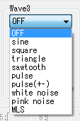
Jan, you can do this with WaveGene - it has 8 oscillators and each one can output to a different channel (if you had an 8 channel sound card!).
It also supports the generation of an assortment of WaveForms and "user wave" (arbitrary waveforms)
.
.
Attachments
Last edited:
You mean the generator also has multiple output channels that do not have to be the same?
As far as I can see the pro upgrade only allows multiple input streams.
Jan
As far as I can see the pro upgrade only allows multiple input streams.
Jan
Last edited:
Best to message John or use the REW forum as I haven't used the Pro version, or have a soundcard with >2 channels, and I don't recall seeing any help/guide for the multi-channel setup that REW provides.
The Pro upgrade supports multi-input capture, it doesn't add extra output channels.REW (pro version licence) allows multiple channels up to what the soundcard can support.
What I meant. Reliably and repeatably measuring very low distortion isn't just slapping a couple of probes on somewhere.
Jan
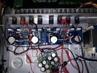
I have a uPC1342V based amplifier (with two pairs of 2SC5200/2SA1493 outputs).
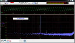
If I measure from the PCB between the output trace and the ground at the input (on the PCB) I measure 0.003% THD.
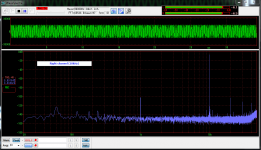
If I measure from the speaker terminals I measure 0.02% THD (mainly second harmonic).
What should I look at to improve the measurement at the speaker terminals? I used 16AWG tinned copper wire (Remington Industries) and I am bypassing the protection relay during the distortion measurement.
Attachments
Does the speaker return line go straight back to the same point as the input ground where you measured first?
You can do step by step working through every solder joint, connector, etc, leaving the ground at the input ground and then working towards the load, see what happens. Draw out the circuit and note all solder joints and connection points, treat those as 'components' in series that can have non-linearities.
Jan
The power amplifier PCBs connects power (+/- & GND) to the rectifier/filter board as does the speaker return from the speaker terminals/protection board. The rectifier board has five ground screw terminals in a row of which two go to the power amplifier PCBs and another is used to connect to the speaker terminals. When I do the 0.02% THD measurement the speaker return goes to the rectifier board as does the ground of the measurement/ADC cable.Does the speaker return line go straight back to the same point as the input ground where you measured first?
For my 0.003% THD measurement I ground the ADC cable on the power amplifier PCB where there is a 2 pin screw terminal for the input. The speaker return is still going to the rectifier/filter board which is a different point. That is likely part of the problem but the rectifier/filter board with the multiple ground screw terminals seems to be the usual connection point for the speaker return. (Or it that a mistake?)
So I guess I could move the speaker return from the rectifier/filter to the power amplifier board (currently it is on the rectifier board). Would that be a good idea?
I guess there is a substantial wire from the connectors at the rectifier board to the point where the input ground is connected? If so than you can move the speaker return to that point near the input ground.
It's all a matter of references.
Jan
It's all a matter of references.
Jan
Yes, it is a substantial wire. I will give that a try.
However I can only do that with one of the two amplifier PCB installed. (Unless I get a new protection PCB that does not join the two speaker returns. That appears to be a common problem with speaker protection board designs.)
However I can only do that with one of the two amplifier PCB installed. (Unless I get a new protection PCB that does not join the two speaker returns. That appears to be a common problem with speaker protection board designs.)
Last edited:
Has anyone here measured 0.002% or better amplifier THD at the speaker terminals with a speaker protection board? [At substantial power levels such as 100W.]
If so, can you please share the make/model and/or photo of the speaker protection board and the speaker terminals that you used?
If so, can you please share the make/model and/or photo of the speaker protection board and the speaker terminals that you used?
Last edited:
Strike up a conversation with diyAudio member Bonsai. I think he may well have opinions, Gerbers, and measured data. Ask him and find out.
Thank you for the suggestion. I sent a PM to Bonsai.
Are you suggesting SS relay or MOSFET based designs? (Is that the best approach for minimizing degradation of THD performance?)
Are you suggesting SS relay or MOSFET based designs? (Is that the best approach for minimizing degradation of THD performance?)
Given the distortion levels I have measured on the L20 V7, MX50x2 and my uPC1342V I wonder how bad the gold colored aluminum cased resistors really are. (I am using one 4 Ohm 100W gold colored aluminum cased non-inductive wire wound.)
The best I have seen on the best amplifier is 0.001% 2nd harmonic. The other "identical" channel is 0.003% and I wonder if I will ever figure out why. (Measured using E-MU 1820m which is 0.0001% loopback.)
At what level (of measured distortion) are the 100W gold colored aluminum cased non-inductive wire wounds a problem?
I have found that wire wound ones in a metal shell for heatsink mount is about same as white cement filled ones or the green wire wound ones. You want metal thin film. Some thin films are metal oxide thin film and those are bad. They will give you 0.02% vs 0.001% for example. Definitely, the big green 100w wire wound is terrible.
The best I have tried are the EBG UXP.
@wtnh, those Caddocks look really nice. Their trade name “Micronox” sounds like it is a metal oxide thin film and not plain metal thin film
Has anyone here measured 0.002% or better amplifier THD at the speaker terminals with a speaker protection board? [At substantial power levels such as 100W.]
If so, can you please share the make/model and/or photo of the speaker protection board and the speaker terminals that you used?
Yes. The SSR’s actually reduces the measured distortion at higher powers. The design by Jhofland is excellent. More info in this thread.
What I meant. Reliably and repeatably measuring very low distortion isn't just slapping a couple of probes on somewhere.
Jan
Once I moved my measurement point from my speaker terminals to my amplifier PCB I was surprised to see how low the THD was on several of the amplifiers that I have built. In other words I was unaware that most of the THD was due to factors outside of the actual amplifier PCB and design. I am seeing 0.0015% to 0.003% THD on several different designs at the amplifier PCB.
So I would encourage others (who are measuring the THD of their project amplifiers) to measure:
1. First across the feedback divider on the amplifier PCB
2. Second across the output and ground terminals on the amplifier PCB
3. Third across the speaker terminals
I was putting 90% of my effort into the amplifier PCB and components and I did not realize the problems being caused by the purchased speaker protection board and the power rectifier/filter board.
I also am finding that I get better measurements with my old Sound Blaster Live! 24 Bit USB (SB0490) then my E-MU 1820m. The E-MU 1820m is vastly superior to the SB0490. However the SB0490 runs from a laptop versus the E-MU 1820m running from a desktop.
Last edited:
- Home
- Design & Build
- Software Tools
- How to - Distortion Measurements with REW