Sorry - I have no access to an AP analyzer - wish I did, otherwise I would not bother with the old EMU. Others in this thread have Victors oscillator and I think they would agree that it is pretty much SOTA. See the old, long thread called "Low-distortion Audio-range Oscillator" here if you have not already seen it. Also, see Toli's DIY page on his use of Victors oscillator here.
Last edited:
wtnh, I was just looking for a shortcut if you had saved a link to a comparison or measurement, given the length of the first forum thread you linked to 😀
From that long thread:
Post #9576 by DNi indicates Victor's oscillator is circa -157.4 and -165.2dBc for H2 and H3 at 2.28Vrms output, when using a notch and an EMU.
Post #9493 by KSTR indicates Victor's 2012 version oscillator is circa H2: -144dB and H3: -138dB at 2.7Vrms, when using an AP SYS2322.
Post #9112 by Bob Cordell indicates his Victor oscillator is at least -145dB THD, depending on loading.
Your plot in post #893 of this thread indicates the harmonics are circa -130dB, so as long as your Victor oscillator is performing nominally then it should be at least -15dB under any EMU0404 USB ADC/input related distortion.
So that then indicates the level of harmonic distortion generated by the EMU0404 USB when acting as an oscillator output, is capable of being lowered to circa -130dB, which is consistent with what I observed in Distortion analysis - a thought experiment.
Last edited:
Just a small addition: I used a 60dB LNA after the notch filter and fed its output to a modded Motu AudioExpress card.From that long thread:
Post #9576 by DNi indicates Victor's oscillator is circa -157.4 and -165.2dBc for H2 and H3 at 2.28Vrms output, when using a notch and an EMU.
Two measurements as of this morning: in the first att the 2nd is at -108dBc, which corrected for the notch attenuation and LNA gain yields -158dBc. In the second plot the oscillator signal is attenuated by 10dB at the notch input, reducing thus the 2nd to -119.6dBc, possibly indicating a small nonlinearity in the notch filter (ideally, it should have been -118dBc).
Regards,
Braca
Attachments
wtnh, I was just looking for a shortcut if you had saved a link to a comparison or measurement, given the length of the first forum thread you linked to 😀
From that long thread:
Post #9576 by DNi indicates Victor's oscillator is circa -157.4 and -165.2dBc for H2 and H3 at 2.28Vrms output, when using a notch and an EMU.
Post #9493 by KSTR indicates Victor's 2012 version oscillator is circa H2: -144dB and H3: -138dB at 2.7Vrms, when using an AP SYS2322.
Post #9112 by Bob Cordell indicates his Victor oscillator is at least -145dB THD, depending on loading.
Your plot in post #893 of this thread indicates the harmonics are circa -130dB, so as long as your Victor oscillator is performing nominally then it should be at least -15dB under any EMU0404 USB ADC/input related distortion.
So that then indicates the level of harmonic distortion generated by the EMU0404 USB when acting as an oscillator output, is capable of being lowered to circa -130dB, which is consistent with what I observed in Distortion analysis - a thought experiment.
Wow - that took some detective work! That thread is a beast. I had not seen Bob Cordell's analysis, but it certainly confirms the quality of Victors oscillator. Presumably, his most recent version (ca. April 2021) is even better. See his post #9407 in that thread here describing the improvements. I got mine from him a couple of weeks ago, so I would think it has the latest goodness.
I have been intrigued with all this distortion measuring stuff ever since reading Bob's DIY article in Audio Magazine in 1981! A copy is on his website here.
Last edited:
If harmonic phases are not stable relative to the fundamental they will see some reduction from coherent averaging. If the fundamental frequency wanders then it is difficult to do any sort of conventional averaging over periods longer than the time for which the frequency remains stable, though I guess it would be possible to track the fundamental and average the tracked results rather than averaging the spectra.I still wonder if the lower frequency stability of an analog oscillator can have some effect on the distortions as measured by REW. John, please may I ask you to shed more light on this? Thanks a lot.
Thanks, John. So just to be clear, if either the analog oscillator and/or the A/D clock exhibits phase noise or jitter (in the case of the A/D clock), that would explain the distortion reduction when turning on coherent averaging?
Last edited:
Would there be any noticeable benefit in tweaking the analog oscillator to align with the REW FFT?
If I generate a 1kHz tone in REW with the 'Lock frequency to RTA FFT (4M)', and use my EMU0404USB (ASIO 192kHz), the RTA distortion display box indicates the fundamental frequency can be either 999.98 or 1000.03 depending on the Frequency value demanded (1000Hz or 1000.01Hz), and using a 4M FFT.
If I use a 256k FFT, the frequency is shown as 999.76Hz for 1000Hz demand. Demanding 1000.2Hz generates a 1000.49Hz fundamental. The reported phase of H2 bounces around between about 86deg and 93deg. If forever averaging is then applied, the H2 phase settles on 90deg, and H2 is about -106dB. Enabling coherent averaging doesn't change the H2 level but does drop the noise floor around H2 by about 20dB.
If you ask REW's generator to lock to an FFT length it will generate tones that are on bin centres, allowing a rectangular window to be used. There is no need to try and force an oscillator onto an FFT bin.
Anything that varies during coherent averaging will converge to its average level. For noise that would usually be zero, hence the reductions there. For harmonics it will depend on how much they vary.
Anything that varies during coherent averaging will converge to its average level. For noise that would usually be zero, hence the reductions there. For harmonics it will depend on how much they vary.
See this post for how I used the balanced XLR inputs to get better results doing amp measurements.
When doing amp measurements do you use specific test clips, screw terminals or solder to the circuit? I am wondering if dissimilar metals (thermocouples) from clips or micro-grabbers cause problems at these very low distortion levels. I also wonder about relay contacts.
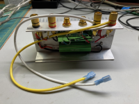
So far, I have pretty much done measurements right from the output terminals on my amps' PCB boards. I tend to use Faston terminals soldered to the PCBs and built a dummy load with female Faston leads.
My dummy load box is pretty crappy and was done quickly. Of course, the binding posts on the load box play into the equation, as do the dreaded green WW power resistors (2x4 Ohms 100 Watts) bolted to the small heatsink.
The RCA jacks are connected to the power resistors through a balanced attenuator set of metal films (1% but not matched). This allows me to feed the balanced inputs to my EMU XLR jack with an RCA to XLR cable I made up.
I will probably scrap this a build a new one with Caddock power film resistors and a trimmable attenuator to get good CMRR into the EMU. At that point, I can experiment with testing at different connection points - the back of the amps, at the end of speaker cables, etc.
Attachments
What is the lowest THD (under high power conditions) that you have measured with your setup?
The reason I am asking is because I can measure low THD (0.0015% one side and 0.003% the other side) on the output terminals of my MX50X2 yet my uPC1342V amplifier seems to be very "difficult" to measure. In the exact same chassis it measured 0.003% on the PCB yet I get 0.02% (almost all 2nd harmonic) at the output terminals. That is just swapping the MX50X2 amplifier boards with the uPC1342V boards into the same chassis, power supply, wiring, etc, everything else the same. I am a little mystified so I will try the balanced attenuator next. (However I can only do that with the E-MU 1820m or 1616m which are attached to a desktop PC. Otherwise I use a Sound Blaster Live 24 Bit USB External with my laptop on battery. The Sound Blaster SB0490 does not have balanced input or output, however. The SB0490 measurements of the amplifier have been a little better and a little cleaner presumably due to the battery power and noise. The E-MU gives a much better loop back THD of the interface but slightly worse measurements of the amplifier with more noise.)
Those RCA jacks look like the ones I bought. Are they a tight fit for RCA plugs or are they loose? (Mine are a little too loose.)
I started with one 4 Ohm 100W load that looks like yours except it is gold color. Last week I experimented with four parallel 16 Ohm 100W loads. (Also gold color.) Did not really make much of a difference. (Certainly did not resolve the 0.02% 2nd harmonic issue.) If anything the four parallel 16 Ohm loads resulted in slightly higher THD.
Later I can try EBG UXP/300 since I ordered two 10 Ohm off of eBay. Not ideal, but I can measured at 5 Ohms or 10 Ohms. (I am mainly interested in 4 Ohms since all my "8 Ohm Compatible" Polk speakers measure at a little less than 4 Ohms with REW.)
It has been about a year since I did any serious amp measurements, and that was on my version of a First Watt F7. Since it is First Watt-like, I was only looking at low levels of power (like 1 Watt haha) and the circuit is not what you would consider super low distortion to begin with. The factory specs are 0.05% THD at 1 Watt, with 2H dominant, so that was what I was shooting for (and did achieve). That amp is very sensitive to component selection and adjustments, so I did spend a lot of time with REW and my EMU setup.
I did do some quick measurements on xrk971's FH9HVX which I built earlier this year in order to verify the predicted LTspice performance of around 0.003 % THD at 25 Watts. Since that circuit has no tweaks other than bias current, I did not carry it further. As I mentioned, I connected the dummy load right at the PCB terminals. I will get back to doing more stress testing on this amp, because I am adding a speaker protection circuit (also from xrk971) and I want to see its influence on THD.
Meanwhile, I am trying to learn more about the best ways to use REW and optimize things with Victors oscillator, notch filters and my EMU. Some of the folks here are way beyond me in terms of experience!
So if I understand you correctly you did measure 0.003% THD at the speaker terminals with the setup you pictured. If that is the case (which is similar to what I measure on the MX50X2) then that is perhaps a confirmation that my technique is "reasonable" for the uPC1342V. I will need to continue to investigate in an attempt to understand why that one is measuring poorly at the terminals but well on the PCB.I did do some quick measurements on xrk971's FH9HVX which I built earlier this year in order to verify the predicted LTspice performance of around 0.003 % THD at 25 Watts.
So next I will build up the differential attenuator you posted and try that.
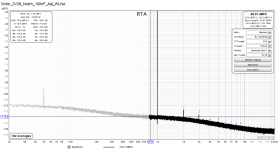
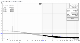
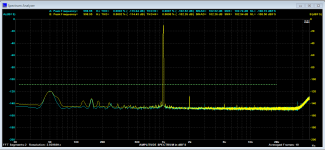
Just a small addition: I used a 60dB LNA after the notch filter and fed its output to a modded Motu AudioExpress card.
Two measurements as of this morning: in the first att the 2nd is at -108dBc, which corrected for the notch attenuation and LNA gain yields -158dBc. In the second plot the oscillator signal is attenuated by 10dB at the notch input, reducing thus the 2nd to -119.6dBc, possibly indicating a small nonlinearity in the notch filter (ideally, it should have been -118dBc).
Regards,
Braca
A preliminary test I did using John Mulcahy's suggested procedure to create a REW Mic Cal file with the notch filter both in the loop and out is showing that Victors oscillator is at least -140dB THD. If I turn on coherent averaging, it drops to -156dB. This is with the oscillator outputting only 1 V RMS into the filter and then feeding the EMU 0404 with a single-ended input, so I need to try some different conditions, but this appears to be consistent with what others have measured. I think I need to upgrade everything to balanced and build an LNA to get the levels up.
See this post for how I used the balanced XLR inputs to get better results doing amp measurements.
So I have done more measurements with the E-MU 1820m that I repaired.
I used the balanced attenuator you linked to (with better than 0.1% hand matched metal film resistors) and I also used two parallel 300W EBG UXP/300 10 Ohm resistors for the load.
Still my measurements are worse than with the little single ended SB0490 and the laptop on battery power. (SB0490 = USB Creative Labs Sound Blaster Live! 24 Bit.)
One data point: 0.003% THD (mainly 2nd) with SB0490 single ended and 0.005% THD (mainly 2nd) with E-MU 1820m and balanced attenuator.
Of course I am looking for about 0.002% THD if this uPC1342V is implemented properly.
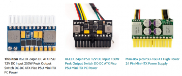
So I was wondering what I could do next (as opposed to buying a new USB interface with XLR). I wonder if I should try using one of the attached automotive to ATX DC-DC converters to run the E-MU 1820m and computer off of a 12V car battery? Good idea? Terrible idea? Not going to help? The idea is to run the motherboard, smallest GPU I have, one SSD and the E-MU 1820m off of the car battery. (Without destroying anything...)
Also I can not say that the two parallel 300W EBG UXP/300 10 Ohm resistors for the 5 Ohm load improved anything. I used 18AWG Belden stranded copper wire for the connections (short). If anything the THD is a little higher than with the 100W gold colored aluminum encased non-inductive wire wound load (4 parallel 100W 16 Ohm resistors).
Edit: Using this PICO ATX power supplies will be a little complicated since I am using a surplus HP Z400 motherboard and they changed the pin out a little bit... Not hard but another step.
Attachments
Last edited:
That is a good idea, however the main issue I am facing is that my good interfaces are PCI card and microdock (connected to PCI card by Ethernet) based.
They are repaired 1820m and 1616m that I bought off of eBay.
The SB0490 measures quite well in loopback but does not have the specifications to really support trying to measure 0.0015% and 0.002% THD (uPC1342V, L20, QUAD405-2 w/OPA228, etc). Note that I use the SB0490 with my laptop. I can't use the 1820m and 1616m with my laptop.
So I wanted to use the much better converters in the 1820m and 1616m to accurately measure the amplifier THD.
By the way I have used my Raspberry Pi4 (with WM8805) to drive my own design PCM1794 and that sounds very good.
I guess I might eventually breakdown and buy something like the MOTU M2 or M4 but I have invested a lot of time and effort into repairing and upgrading the E-MU PCI and microdock based systems.
Last edited:
I think any desktop/deskside PC is going to be problematic as far as generating some noise goes. Just the nature of the beast, so putting a PCI soundcard inside that environment is bound to hamper efforts to get really low numbers. I have also seen notes from people about Raspberry Pis, especially the 4, as being noisy as well, both conducted and radiated noise. It's not just the CPU and the internal power supplies - it's everything connected like the monitor and keyboard.
I also see lots of FFTs posted with significant 50/60 Hz bumps (and other harmonics) due to noisy wall-wart power supplies, which I why I run my EMU 0404 on a 5V Lithium battery and float it and my laptop from what I am measuring. That seems to help lower the baseline.
One thing I have thought about is using a USB isolator. I am not sure if they have the bandwidth needed for USB soundcards, but might be a consideration in isolating the computer.
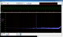
I don't have any noise issues with my PC at all.
This is a line stage I measured recently- there is some 50hz pickup due to lack of screening.
The second screenshot is a loopback measurement.
The only time I have issues is when a ground loop is formed, and I have an ADC with isolated USB to deal with that.
This is a line stage I measured recently- there is some 50hz pickup due to lack of screening.
The second screenshot is a loopback measurement.
The only time I have issues is when a ground loop is formed, and I have an ADC with isolated USB to deal with that.
Attachments
The good thing about a spectrum plot is that hum spikes often have no bearing on the measurement other than making them aesthetically unpleasant to some. One channel of the EMU 0404 USB has a similar issue - I know where the spikes are, but I don't need to eliminate them to typically make a meaningful measurement.
- Home
- Design & Build
- Software Tools
- How to - Distortion Measurements with REW