I wouldn't call it a false trigger. The boards detect DC and do there job. It is just one amp that needed a little more settling time. Must have been right on the edge and some boards tripped some didn't.
My symasym type input stage used to take a little longer to settle before I
fixed the servo component values.
I just extended the final mS time constant in the 21'st (s) script to accommodate the slow settling time.
PS - all the other time constant's in the protection circuit's main loop (inrush,etc) , can be customized to match your hardware perfectly.
Mine is still flawless (operation) after 1000's of events - awesome
circuit/project !!
I would like to update to my "purple board 21'st" to see if I can stillo build things.
EDit - bigger caps in the analog DC detect circuit will also the extend-increase moment to moment
DC sensitivity but expose the speakers to more miliiseconds of a DC condition.
OS
Last edited:
Did you run dual supplies in you amp? If so you should update to one of the later designs that isolate the supply grounds. No more ground loops that way.My symasym type input stage used to take a little longer to settle before I
fixed the servo component values.
I just extended the final mS time constant in the 21'st (s) script to accommodate the slow settling time.
PS - all the other time constant's in the protection circuit's main loop (inrush,etc) , can be customized to match your hardware perfectly.
Mine is still flawless (operation) after 1000's of events - awesome
circuit/project !!
I would like to update to my "purple board 21'st" to see if I can stillo build things.
EDit - bigger caps in the analog DC detect circuit will also the extend-increase moment to moment
DC sensitivity but expose the speakers to more miliiseconds of a DC condition.
OS
Did you run dual supplies in you amp? If so you should update to one of the later designs that isolate the supply grounds. No more ground loops that way.
I never knew about those. The purple board is 3.3 or something (the ones you
sent to thimios). I fits perfectly as a replacement for the ones you gave me - 3.2??
Mine (present) are the ones with the little daughter cards for the MOSFETS/
opto's.
I'm not having any hum issues. My supply is a dual and my DC is referenced
from a lifted ground ( for the protection PCB only). I have slipped probes
and even burnt one OP device .... DC (mosfets) fired/triggered immediately.
No issue beyond wanting to build again and the better layout + compatibility
of the new board.
OS
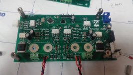
I don't remember which ones Thimios built. If they have the speaker relays on board, the speaker relays join the speaker grounds of both amplifier channels together. The newer versions with the separate speaker relays have the amplifiers optically isolated from the control boards, so grounds are completely separate. I found these are a lot easier to make a quiet amplifier.
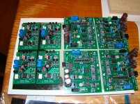
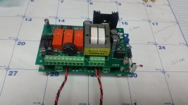
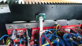
These are going into service in my monoblocks. Unfortunatly I blew D5 on the atmega on one of the boards, so I have to replace the chip. It's gonna be interesting to remove and solder a new atmega with fully populated board.
Attachments
You should use a hot air rework station for best results, but I've had luck in the past either blobbing lots of solder on and bending the leads up, or cutting the IC off with a grindwheel on a die grinder or Dremel, then removing the leads. Hot air stations are cheap and really hand for heat shrink.
https://www.amazon.ca/WEP-858D-Sold...1422&sr=8-2&keywords=rework+soldering+station
https://www.amazon.ca/WEP-858D-Sold...1422&sr=8-2&keywords=rework+soldering+station
I plan to use a hot air gun on minimum fan speed to remove the old ic. I hope the surrounding components stays in position. Do you have more of these boards in stock in case I mess up the board?
You will need to concentrate the heat from the heat gun. A tinfoil funnel might work. I usually preheat with an iron and a big tip first. Lay a lot of solder on, then add more with hot air until the IC is free. Don't pull the IC, traces will come with it. Get it hot enough to fall off.
Another option would be to cut the trace to D5 and jumper it to D6 or D7. It's easy to alter the software to run from another pin.
I keep lots of boards in stock if you make a mess.😀
Another option would be to cut the trace to D5 and jumper it to D6 or D7. It's easy to alter the software to run from another pin.
I keep lots of boards in stock if you make a mess.😀
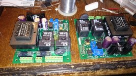
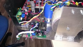
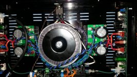
My latest version for the VHex amps is a stacked version that mounts on a 2U rear cover and has everything on board. I've put some time into lowering current consumption, so I can get away with a much smaller transformer and regulator heat sinks. This one barely warms up.
Attachments
Last edited:
I've made a small rear panel USB to serial adapter for programming these. http://www.diyaudio.com/forums/soli...century-protection-board-139.html#post4816867
I don't remember which ones Thimios built. If they have the speaker relays on board, the speaker relays join the speaker grounds of both amplifier channels together. The newer versions with the separate speaker relays have the amplifiers optically isolated from the control boards, so grounds are completely separate. I found these are a lot easier to make a quiet amplifier.
They do , but I just run the active amp to speaker through the PCB euro terms (MOSFET relays).
The speaker grounds go right to my main chassis star.
The protection circuits analog DC detect's ground reference is a small 20ga
wire that runs separately to the main star.
The protection circuits main ground is separate still from the three I already mentioned and is lifted with a 4.7R film resistor.
I have no hum , no ground connection through any PCB or relays.
OS
If both your supplies connect to a common star ground, there's no advantage to the new board. The new design with optos is for dual mono amps with dual star grounds.
What I never understand is this discussion of the separate star grounds or a single star ground. It seems that even with the separate star grounds that as soon as you go back to the power outlet or somewhere not far from that point the two separate grounds will merge at some point, so isn't that just a larger loop area but still a loop that connects both ground sides together? Wouldn't the single star ground have the least loop area to contend with?
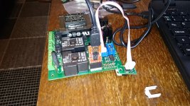
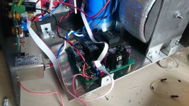
I desoldered and bent away D5 and blobbed some solder on to short the pad to D6, changed the code and tested. That worked. 🙂
Now I have a strange problem.
The amplifier starts fine with no load connected, but when I plug in my subwoofer, it trips on DC offset after a few seconds.
If I start the amp with the subwoofer connected, it goes through the startup sequence, then i get a slight thump in the subwoofer before it shut off.
If I start the amp before I connect the woofer, it will play bass for a few seconds before it trips on DC offset.
Any suggestions what causes this?
Edit: Never mind. It's caused by real DC. The relay won't hold in when It's going through the resistor, shutting down the transformer. I'll have to change the code again to keep it from switching off. 😉
Attachments
Last edited:
You should try lowering the value of that resistor. I still haven't taken the time to thoroughly test values there. I had no 320R when I assembled the prototype, so I installed 220R and haven't had any issues.
- Home
- Amplifiers
- Solid State
- How to build a 21st century protection board