If you are using my supply with the 12 pin I2C connector, the transformer connections are confusing.
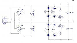
That is interesting, as I only have 3 leads from my transformer. 36-0-36
But as it happens on the version I have got, the two middle ac connectors are connected together - registers as short on the multimeter. So I have connected the centre wire to them.
The outer wires are connected to either end. there is a 76V potential difference between the two outer secondaries.
The outer wires are connected to either end. there is a 76V potential difference between the two outer secondaries.
I don't think this supply will work with a center tap transformer
Attachments
Last edited:
You're using a center tap transformer then. If you can email me a picture of the supply, I'll double check to make sure I sent you the correct supply and it will work for you. From what you are explaining, it sounds like the supply is shorting your transformer.
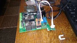
Attached is the photo of the supply. Notice that the two centre AC connectors are on the same physical track. I thought to me it looked like it would be OK with a centre tapped transformer, but I could be mistaken..


Let me dig through my bins in the morning. I think I may have sent you some bad boards by accident. If you look at that schematic, D2 and D3 will be a short for the transformer. If I sent you boards to match that schematic, that would explain your problem.
Did you test each stage of the build using a Mains Bulb Tester to power ON?Is your transformer connected to the supply correctly?
Yes I believe so, as long as the GOSS screen should be earthed, that is the only thing I am not sure about. It measures 76V across the 36-0-36 secondaries when checked.
Did I send you the supply or is it your own?
Yes, it is from the kit. It is a compact supply board.
It actually runs fine with just the relays and transformer in play. It's only when adding the supply that the issue occurs.
I'll take out the supply board and have a good look over it at the weekend. ensure everything is installed correctly / check voltages at various points on the board and then reply again.
230r of soft start resistance suits a 100VA to 150VA 230Vac transformer.
For a 700VA 230Vac I would use 30r to 40r with a T3A mains fuse.
Thanks all I think that the board I have is bad according to Jeff. I'm going to check tomorrow and if the only electrical problem is the diodes then I'll run those point to point off board.
I think the output voltage markings on the silk screen may be wrong too but I've not got far enough to confirm. If they are the only two faults I can fix both issues and move on.
I think the output voltage markings on the silk screen may be wrong too but I've not got far enough to confirm. If they are the only two faults I can fix both issues and move on.
Jeff if you have another of those boards handy please could you check the mosfet control elements are correct.
Jeff if you have another of those boards handy please could you check the mosfet control elements are correct.
It looks like my helper disposed of my good boards and kept my junk ones. You have a PM.
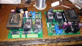
I've got the PSU boards working temporarily by building a small bridge circuit off the board. Jeff is going to send me some new replacement boards but I'm working up until then. Speaker protection boards also now assembled and tested.
First time around they tripped with dc offset, and there was indeed 1.2v of offset as I had not calibrated that channel!
All good now, will put up some photos when tidied up a little. Thanks for all the help so far!
First time around they tripped with dc offset, and there was indeed 1.2v of offset as I had not calibrated that channel!
All good now, will put up some photos when tidied up a little. Thanks for all the help so far!
Flashing bootloader on my single supply boards the ghetto way. The ICSP programmer I ordered from ebay didn't arrive in time
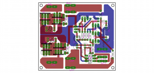
Now the boards are ready to be fully populated. 🙂
At the same time I flashed bootloader to a new atmega 328 for the uno board.
Now the boards are ready to be fully populated. 🙂
At the same time I flashed bootloader to a new atmega 328 for the uno board.
Attachments
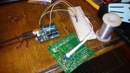
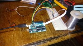
Flashing bootloader on my single supply boards the ghetto way. The ICSP programmer I ordered from ebay didn't arrive in time
Now the boards are ready to be fully populated. 🙂
At the same time I flashed bootloader to a new atmega 328 for the uno board.
Are the board shown in the first photo available for purchase anywhere? Thanks
Are the board shown in the first photo available for purchase anywhere? Thanks
Virtual Zero Audio - power amplifier products
hi jwilhelm,
can the dc protect board used alone , if possible , can you share the gerber file via PM, iam about to print mr apex speaker protect attached below
can the dc protect board used alone , if possible , can you share the gerber file via PM, iam about to print mr apex speaker protect attached below
The DC protection boards need to be connected to a microcontroller to work properly. The SS relays will never turn on without the controller telling them to.
You need to get your I2C addresses first, and enter them in the software. The latest software is in the mail. The little relay can be really annoying until the final software is loaded. Sometimes it buzzes.
- Home
- Amplifiers
- Solid State
- How to build a 21st century protection board