A 6 cap board would likely fit. My supply actually holds 8 per channel, 2 boards of four joined with CRC resistors. The schematic is below. I'll try to get some better pictures.
Grounding is simple, just return all your grounds to each supply (amp output, amp input, and speaker return). If you are using dual transformers, treat each channel like a separate amplifier. Add a separate ground loop breaker to each supply ground.
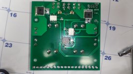
SMT is very easy to work with. It just takes a bit of practice. Tack down one pin, warm that pin back up and align the part. Once it's straight, solder the rest.
Grounding is simple, just return all your grounds to each supply (amp output, amp input, and speaker return). If you are using dual transformers, treat each channel like a separate amplifier. Add a separate ground loop breaker to each supply ground.
SMT is very easy to work with. It just takes a bit of practice. Tack down one pin, warm that pin back up and align the part. Once it's straight, solder the rest.
Attachments
A 6 cap board would likely fit. My supply actually holds 8 per channel, 2 boards of four joined with CRC resistors.
Oh, that's clever. I didn't realize that the PSU boards are not identical.
Is it something like I commented in the picture attached?
If my capacitors fit your boards (I have these HC2A688M40050HA SAMWHA - Capacitor: electrolytic | TME - Electronic components ), maybe I can use your boards and make two separate smaller boards holding two extra capacitors?
Or is it too complicated?
How important is to have the quick power shutdown PSUs in your opinion? Is it worth it to sacrifice capacity to have rail shutdown, or should I have maximum capacity without controlled rails?
Thanks a lot.
Attachments
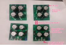
Yes the resistors are the bottom below the mount bracket. There's also bleed down resistors and ground links. They use TO-220 rectifiers that mount under the input board to the mounting bracket for cooling. The quick shut down circuitry is on the bottom side of the output board. it looks like your caps use 22mm 4 hole mounts. I've got these boards laid out for 35mm snap in caps with 10mm spacing, so they won't work with those caps.
Attachments


OK, I get the idea. Very nice work.
I don't see from the photo how did you mount the main transformers to the front panel. I suppose it's not a big bolt going through the panel ... 🙂
I sent a PM regarding the board set.
Thanks
I don't see from the photo how did you mount the main transformers to the front panel. I suppose it's not a big bolt going through the panel ... 🙂
I sent a PM regarding the board set.
Thanks
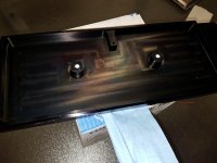
Perfect!I make my own chassis. I mill the front cover from 1" flat bar and leave a couple threaded bosses in the back of it to mount the transformers. They're blind holes so there's nothing showing on the front.

It can also be connected to a pair of emitter resistors for current sensing, but can also connect with I2C current sensors.
Just came across this thread while researching protection systems for my project, and I would like to ask how you'r implementing Current sensing as I'm not clear about how to connect this? Bearing in mind that my lateral Mosfet output transistors don't have emitter resistors. A diagram/pic would help.
Seb
The current sensing is done by measuring voltage drop on the emitter resistors, which obviously isn't going to work in your situation.
I'm in the process of figuring out the best way to add Hall Effect current sensors to the supplies as an alternate option for current sensing. This could be an in series module with the supply rails too. One option I'm looking into is a ACS758. It could be connected to one of the AD converters on the Atmega328, but would require two AD converters per channel (yuck!). Another option would to use a comparator and have it tie into the existing current detection input. I'll likely go with the latter when time permits.
I'm in the process of figuring out the best way to add Hall Effect current sensors to the supplies as an alternate option for current sensing. This could be an in series module with the supply rails too. One option I'm looking into is a ACS758. It could be connected to one of the AD converters on the Atmega328, but would require two AD converters per channel (yuck!). Another option would to use a comparator and have it tie into the existing current detection input. I'll likely go with the latter when time permits.
Attachments


Hello
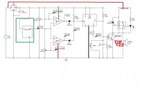
greetings found this on the net current sensing coil used with comparator
warm regards
Andrew
That's similar to what I'm trying to do, but my way is much more compact. The little Hall Effect sensors won't be emitting a magnetic field as another bonus.
Hello jwilhelm
greetings have tried it with ACS712 current control works will upload schematic
warm regards
Andrew
greetings have tried it with ACS712 current control works will upload schematic
warm regards
Andrew
Hello
greetings this schematic is the work of my friend from this forum
tomas rozario who helped me to make this project a sucess
warm regards
Andrew
That's similar to what I have in mind but I'll be tying it into the control board instead of using a relay.
Hello
greetings your protection is very sophisticated i just try to do a poor mans version
but one day i will try your solid state relay in my current control protection the
ELCHEAPO version
warm regards
Andrew
greetings your protection is very sophisticated i just try to do a poor mans version
but one day i will try your solid state relay in my current control protection the
ELCHEAPO version
warm regards
Andrew
This protection system does add up fast! It's as expensive as the amplifier boards themselves, but it's much cheaper then the average speakers, so money well spent.
Hi,
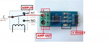
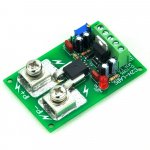
Boy it is a long time. I already forget about it. It is a simple circuit for those that does not want to use a micro. Also it isolated the amplifier output from the circuit and the best it is cheap to built. Suggestion next time make sure that the current sensor has mounting holes. The first ones I overlooked it and I had to glued it to a pieces of isolation material to be able to mount it. Also you can buy it up to 200 amps.
Boy it is a long time. I already forget about it. It is a simple circuit for those that does not want to use a micro. Also it isolated the amplifier output from the circuit and the best it is cheap to built. Suggestion next time make sure that the current sensor has mounting holes. The first ones I overlooked it and I had to glued it to a pieces of isolation material to be able to mount it. Also you can buy it up to 200 amps.
Hi Tauro
It does look like a nice standalone design. If you could squeeze DC offset detection in with it, it would be a great option for complete speaker protection.
I'm also looking to add mine to the supply rails instead of the output. I would prefer to monitor the current going into the amp as opposed to out as a complete protection package.
That was actually a 100 amp version in my picture. It's going into a big constant current power supply whenever I can get back to that project.
- Home
- Amplifiers
- Solid State
- How to build a 21st century protection board