Carried out some more measurements today.
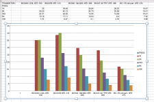
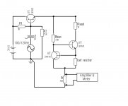
I have compared the results of 5 bipolar transistors I had lying around. In each case it is only the transistor that the signal passes through that was changed, I will refer to this as the CCS transistor. The other transistor that acts as an error amplifier, i will refer to as the feedback transistor. In all cases the feedback transistor is a bc549c with a 39K load resistor.
The DC conditions in each case were identical and were as follows:
Vs = 30.0V, ICC's = 1.0mA, Vccs = 15.2V
The current sense resistor was 10K 1%
The input voltage (AC) was 1.033 V RMS
See attached for results:
Attachments
Last edited:
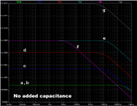
I simulated the current sources, "before" and "after".At output impedances > 10 MOhm a picofarad is important.
For example 1 pF at 10 KHz has 16 Mohm impedance.
"before" is as shown in Kolinummi's book.
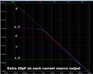
"after" is with an additional 20 picofarads (to AC ground) on the current source output node.
If the goal of the current source is to provide excellent PSRR in a differential stage, to reject huge amounts of 120Hz ripple on the supply rails, then there is a quite substantial improvement between the worst and the best.
Attachments
Can you share the simulation file, as i have no clue what you are simulating?
Professional designs for measurement purposes let the power supply float to increase
PSRR.
Professional designs for measurement purposes let the power supply float to increase
PSRR.
In post #44 peufeu suggested the following scheme to measure PSRR:
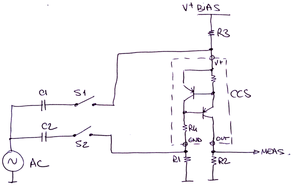
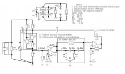
I have come up with my own scheme to fit in with my existing setup ( the notch filter would probably need to be bypassed though )
See attached, the CCS power supply has 100/120 Hz ripple superimposed.
I have come up with my own scheme to fit in with my existing setup ( the notch filter would probably need to be bypassed though )
See attached, the CCS power supply has 100/120 Hz ripple superimposed.
Attachments
... i have no clue what you are simulating?
I am sorry to hear you have no clue. Perhaps this post might help.
The first concept to grasp is
- Kolinummi's book p.130 shows simulations of six different current sources: simulated impedance versus frequency. His results are posted here in this thread, as the attachment to post #273.
- I replicated those simulation results. My replication is shown here in this thread, as the first attachment to post #282.
{You will see that the horizontal axes of my plots begin at 0.001 Hertz instead of 1.0 Hertz. Don't let that confuse you.}
After you thoroughly comprehend the first attachment to post#282, we have a foundation from which to begin comprehending the second attachment.
I am sorry to hear you have no clue. Perhaps this post might help.
The first concept to grasp is
The second concept to grasp is
- Kolinummi's book p.130 shows simulations of six different current sources: simulated impedance versus frequency. His results are posted here in this thread, as the attachment to post #273.
Take some time and compare the two figures: #273 fig1 and #282 fig1. Look at the low frequency impedances, extrapolated back to DC. Do they match? (answer: yes). Look at the corner frequencies, where the curves start to decrease at 1 decade of resistance per decade of frequency. How closely do they match? (your answer goes here)
- I replicated those simulation results. My replication is shown here in this thread, as the first attachment to post #282.
{You will see that the horizontal axes of my plots begin at 0.001 Hertz instead of 1.0 Hertz. Don't let that confuse you.}
After you thoroughly comprehend the first attachment to post#282, we have a foundation from which to begin comprehending the second attachment.
I think what Udo is requesting and that I am requesting to see is the actual schematics of the various current sources refered to in the graphs.
The link in post #273 only takes you to a page that let's you buy the book, you can't actually view it.
At the very least I really want to know the details of the clear winner, that is configuration "g" Thanking you in advance.
Gordon.
Last edited:
I measured the response of the amplifier / notch filter and substituted the measured gain into the formula for impedance. Yes I was surprised how much attenuation the notch filter yielded so far from its center frequency, is this a flaw of this particular type of notch filter ( Hall notch filter ) rather than the usual twin tee type?
Gordon.
P.S. Regarding simulation results: Do the transistor models not include parasitic capacitances, considering the suggested impedances from the simulation results it doesn't look like it. I only have a very basic simulator on my android tablet ( My PC is broken ) and I got pretty similar results to my experiment for a 500 microamp ccs, but for the 5mA ccs the result was considerably higher than in the experiment. Impedance falls with increasing test frequency so the transistor models must include capacitive elements, however transistor parameters that can be varied in the simulator are pretty limited and there is no provision to adjust capacitive parameters, strangely though it allows you to do that with diodes!
If you're interested, here it is ( It runs on Apple OS, Android and Google Chrome ):
EveryCircuit
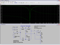
I attached a better notch filter which does not have the problem of your filter. This is an active Twin-tee notch with 20 dB of gain.
You can use it instead of your notch filter and your second gain stage.
You can adjust the notch width with R5. R5 + R7 should be 111 Ohm. Gain A = (R6 + R5 + R7) / (R5 + R7).
I see that you use TL072. For these the 1k load is too low - use x 10 for the the gain resistors (I did edit the circuit already).
The transistor models do include parasitics, but the models have limitations regarding 2nd and higher order effects.
Often the spice model are automatically generated without love for details.
PCB and package parasitics are generally not included too.
This is fine as long as you are in the valid region of the model. For a current source > 1 GOhm this is definitively not the case.
Attachments
Last edited:
Thanks for the notch filter, that looks much more agreeable.
Not sure which 1K you are referring to the gain setting resistors are 91K & 10K respectively. See post
#288.
Gordon.
I see that you use TL072. For these the 1k load is too low - use x 10 for the the gain resistors (I did edit the circuit already)
Not sure which 1K you are referring to the gain setting resistors are 91K & 10K respectively. See post
#288.
Gordon.
Sorry for the confusion.
I posted a first version of the notch filter with R6 = 1k. This is too low if you are using the TL072, they can not drive them.
So i changed R6 to 10k in the posted 2nd version of the notch filter.
If you are after precision replace the TL072 by LM4562.
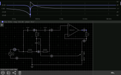
Attached is a version of your circuit with the new notch. It goes down to 1 Hz, so you can measure impedance at really low
Hz. This may be important for the 1TOhm current source mentioned in an earlier post.
I changed the gain of each opamp from x10 to x34 to increase sensitivity. CCS Impedance is (34*34) / V(out).
Best,
Udo
I posted a first version of the notch filter with R6 = 1k. This is too low if you are using the TL072, they can not drive them.
So i changed R6 to 10k in the posted 2nd version of the notch filter.
If you are after precision replace the TL072 by LM4562.
Attached is a version of your circuit with the new notch. It goes down to 1 Hz, so you can measure impedance at really low
Hz. This may be important for the 1TOhm current source mentioned in an earlier post.
I changed the gain of each opamp from x10 to x34 to increase sensitivity. CCS Impedance is (34*34) / V(out).
Best,
Udo
Attachments

Last edited:
Thanks Udo. The LM4562 is fantastic! Just looked it up and was surprised that Mouser sell them for only £1.85. I was away from electronics for several years and I'm still catching up with the vastly superior technology now available. I think probably the best opamp I have around are TLE2141, do you think they would be OK to use in your circuit?
BTW, what is the tolerance of the capacitors in the notch filter?
Gordon.
EDIT: The TLE2141 looks OK apart from being more noisey. ( I have 2 just in case you were wondering )
BTW, what is the tolerance of the capacitors in the notch filter?
Gordon.
EDIT: The TLE2141 looks OK apart from being more noisey. ( I have 2 just in case you were wondering )
Last edited:
You can keep the TL072 and upgrade later to LM4562 or LT1469. LME49990 or AD797 are still better in some aspects for low sources.
But even NE5532 would be a big improvement over TL072.
1% would be great, NPO or PP best. As smaller the notch BW as more comes the tolerances into play.
I changed the 200 nF to 202 nF and did not notices a great change but 205n is not so good.
31k831 = 30k+1k8
15k9155 = 15k+910
is Ok.
I am looking forward to see more measurements with typical VAS transistors with higher Vce and with other CCS.
Best,
Udo
Last edited:
With such high values of 2x318k at the + input a JFET opamp is the only option.
The penalty is that noise and common mode distortion go up.
Better to use a bigger 2% Cap (Vishay BFC241641004).
The penalty is that noise and common mode distortion go up.
Better to use a bigger 2% Cap (Vishay BFC241641004).
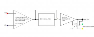
I was thinking about building a general purpose laboratory amplifier. It could be used in the CCS impedance measurement project, but could be used again for other purposes.
I have compiled a block diagram of the basic idea. I might consider adding an optional low pass filter and a precision rectifier as well. Any thoughts on this idea are welcome.
In case you were wondering, I already have a PGA103 and its a pretty good spec programmable gain amplifier. It has full power bandwidth to 250Khz with x100 gain, higher for x10 and x1. The output is good for driving capacitive loads too.
Gordon.
Attachments
With such high values of 2x318k at the + input a JFET opamp is the only option.
The penalty is that noise and common mode distortion go up.
Better to use a bigger 2% Cap (Vishay BFC241641004).
I never thought about it that way. At the moment spending any money ( even for 3 or 4 capacitors is not an option. So for now at least I might try and find 5% caps that are within 2% by measuring them, until I can get the suggested ones.
Thanks again Udo.
Gordon.
I forgot that I bought an MC33079 recently. This would appear to be adequately specified. Low noise & distortion and wide bandwidth.
As this part has 4 amplifiers, I am going to split the gain between 3 x 20db sections, one of which will be Udo's notch filter with +20db passband. This will allow the choice of either 40db or 60db overall gain giving the setup a wider dynamic range. 3 stages will also increase the overall bandwidth and keep distortion down at higher frequencies ( due to more negative feedback per gain stage )
I have a spare opamp on the mc33079 that I could use as a low pass filter if noise is a problem when measuring very high Z current sources.
Gordon.
Last edited:
Look up Samuel Groners Opamp Distortion investigations.
He did not recommend the MC33079/78.
This is certainly interesting, a lot of information to digest, but it's certainly opened my eyes.
Any thoughts on using the TLE2141 as I think it's probably the best I have available for now?
- Status
- Not open for further replies.
- Home
- Amplifiers
- Solid State
- How do you calculate impedance of a current source?