Hello David,
I had a small free time today and I played a little with the new CH2 model, While I still wasn't able to implement this variant using FreeCAD, I think I can confirm the benefit of having it for what concern the possibility to reduce noise from the port.
See attached feedback inside PDF file.
Thanks again to make this model possible.
Attachments

Hi Marcelo,
An excellent analysis!
Your expectation that the particle velocity will be increased at the S4 constriction in the CH2 model is correct. The value is also close to that for the CH1 Horn 2 throat, as you assumed - see attachment.
Many thanks for the feedback, I will certainly see what can be done about the things you have identified, and will try to also include the S4 velocity and pressure values for CH2 in the next update (not today's).
In the PDF file, the heading for the second system model should read CH2 not CH1... 🙂.
Kind regards,
David
Attachments

Last edited:
Hornresp Update 5460-230329
Hi Everyone,
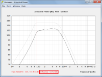
CHANGE 1
When two sets of acoustical power or acoustical pressure results are being compared and the chart is clicked, the difference in decibels between the two traces is now included in the sample information, as shown in Attachment 1.
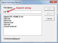
CHANGE 2
The functionality of the File Import / Export form has been enhanced to include an integrated file search and "shortlisting" feature, as shown in Attachment 2. This makes it easier for example, to find the required file to import if the Import folder contains a significant number of files.
BUG FIX
It is no longer possible to specify a closed mouth on OD2, PH1, PH2, PH3, PH4, CH2 or CH3 designs.
Kind regards,
David
Hi Everyone,
CHANGE 1
When two sets of acoustical power or acoustical pressure results are being compared and the chart is clicked, the difference in decibels between the two traces is now included in the sample information, as shown in Attachment 1.
CHANGE 2
The functionality of the File Import / Export form has been enhanced to include an integrated file search and "shortlisting" feature, as shown in Attachment 2. This makes it easier for example, to find the required file to import if the Import folder contains a significant number of files.
BUG FIX
It is no longer possible to specify a closed mouth on OD2, PH1, PH2, PH3, PH4, CH2 or CH3 designs.
Kind regards,
David
Attachments
It's an "AND" of both non-zero Vrc/Lrc & the OFP stuff that toggles it -- and that works right. The CH1 (proper) uses the Vrc/Lrc for a throat chamber (or not if you leave it zeroed-out). Both are useful. I can't look hard at this right now and will have to catch-up later tonight--just wanted to post how it works.
Last edited:
Hi Marcelo,
Do you happen to know the sequence of events that leads to CH1 being shown with Ap and Lpt instead of the correct labels Ap1 and Lp?
I have been trying to replicate your screenprint attached, but keep on getting Ap1 and Lp.
Thanks,
David
Hello David,
Probably it was a mistake from my side, in general I modify existing macros files to generate new one, so eventually it doesn't match properly Hornresp model, witch is this case.
AP and Lpt is generate from in the FreeCAD macro while creating the *.txt file, so while importing from Hornresp it abuses Hornresp exploit 🙂 Some errors Hornresp can detect and don't import data so it warn me to looking for incorrect data.
In the PDF file, the heading for the second system model should read CH2 not CH1...
True, when our hobby are complicated and our attention is reduced after work, strange things happen as all above 😀
Regards,
Marcelo
in general I modify existing macros files to generate new one
That explains it then.
I checked the code and the only way that it can possibly happen is if the data in the file record itself is manually changed by the user, which in effect is what you have done.
when our hobby are complicated and our attention is reduced after work, strange things happen
So true 🙂.
Hello!
I just downloaded Hornresp in order to simulate a midrange front loaded horn.
I thought I'd start off with modelling a horn that I've already made to get going with the program.
Now, this is a horn with a dome tweeter, which I understand can be a little tricky. The flare is very simple though -it's just a one section 11 degrees conical horn about 76cm long. In reality it has a kind of a lip section at the end which does smooth out the response a bit below 3kHz. I can take a measurement without the "lip", but I want to try to get in the ballpark with the simulation first.
I was wondering if you could help me get closer to the real world results. Perhaps some parameters are way off, or I need to change some settings?
I changed the front (adapter?) volume or whatever it's called to 0. I don't know the specs of the rear chamber inside the tweeter of course, so I just put in some small numbers there.
The real world measurements (1st pic) are made with REW. It has no smoothing and it has the maxiumum (500ms) window, because my room is so highly damped (and the horn so directional) that windowing only makes the resolution worse.
The absolute SPL is not calibrated. The level is probably much lower in reality.
Hello guys, trying to simulate a bass reflex cab around this driver: https://www.sbaudience.com/index.php/products/woofers/bianco-10mw150/
The driver specs claim 65-5000 hz but I cant even get it up to 1000 hz without dropping off badly. Am I doing something wrong in my simulations? Included picture and wanted to include hornresp file if someone can check it out for me but it did not want to upload. The store that sell the driver claim it will reach 2000 hz with a good wide pattern (about where I want it to be to cross to a tweeter). Thanks for any help.
The driver specs claim 65-5000 hz but I cant even get it up to 1000 hz without dropping off badly. Am I doing something wrong in my simulations? Included picture and wanted to include hornresp file if someone can check it out for me but it did not want to upload. The store that sell the driver claim it will reach 2000 hz with a good wide pattern (about where I want it to be to cross to a tweeter). Thanks for any help.
Attachments
Perhaps some parameters are way off, or I need to change some settings?
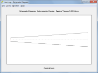
1. Check the horn parameter values, they are not correct - see schematic diagram attached.
2. Check the driver parameter values, they are also not correct - does the Spec sheet for the driver give a Vas value somewhere?
Attachments
The driver specs claim 65-5000 hz but I cant even get it up to 1000 hz without dropping off badly.
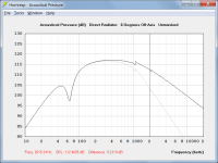
It's because the power response is being calculated, not the pressure response.
The pressure response of the driver can be calculated by selecting the Tools > Output > Direct Radiator menu commands from the Acoustical Power window and then selecting Tools > Directivity > Response. This will give you an idea of how the system will perform when driver directivity is taken into account.
wanted to include hornresp file if someone can check it out for me but it did not want to upload.
To export a record, select File > Export > Hornresp Record from the main Input Parameters window.
Attachments
Thank you David. When simulating higher frequencies in bass reflex enclusures (and maybe horns too?), is it fair to say that pressure response is of more importance than power response? Is it possible to monitor the on-axis pressure response while in the loudspeaker wizard making changes to the cabinet?
When simulating higher frequencies in bass reflex enclusures (and maybe horns too?), is it fair to say that pressure response is of more importance than power response?
The pressure response is required if directivity effects are to be taken into account. Hornresp has limited capabilities in this regard.
Is it possible to monitor the on-axis pressure response while in the loudspeaker wizard making changes to the cabinet?
Not for a bass reflex enclosure.
It is also worth noting that Hornresp (and most other speaker simulators) assumes the driver behaves like a rigid plane piston. In reality the diaphragm will flex quite a bit, giving rise to peaks and dips in the response at mid- to high frequencies. The power response will not be similar, but the pressure response can be widely different. Hornresp on-axis response pressure response for a piston would be essentially flat if voice coil inductance was ignored, since the beaming of the piston compensates for the mass rolloff of the power response. But VC inductance adds additional rolloff. Sometimes the cone is designed to compensate for this, to extend the response.
For tuning a bass reflex enclosure, you're mainly interested in the range where the pressure response and power response are the same (where the driver is omni-directional) so you don't need to worry about the difficulties above. For the MF-HF range, using the curve in the driver datasheet (or your own measurements) is better.
For tuning a bass reflex enclosure, you're mainly interested in the range where the pressure response and power response are the same (where the driver is omni-directional) so you don't need to worry about the difficulties above. For the MF-HF range, using the curve in the driver datasheet (or your own measurements) is better.
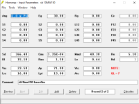
I am designing a front loaded exponential mid bass with a celestion TF0510 (cone) 5" driver.
Desired range is 200 to 900 Hz.
This is what I managed to obtain with the "Tools --> System design --> With driver" utility from the input parameters window.


Seems good enough but I have two questions:
1. According to David Mc Bean suggestion a few post above, I tried to check the pressure response of the driver by selecting the Tools > Output > Direct Radiator menu command from the Acoustical Power window, but the command "Output" is greyed out and cant be selected. How do I check pressure response and is it needed ?
2. I have managed to import the horn data into skecthup after making it rectangular. Now, this horn should be "bent" at 90° at some point due to space constraints, so the driver stays behind the woofer cabinet as it points up.
I can easily "bend" the horn by progressively rotating the width segments of the side profile, handling them by their center. Let's say for the sake of argument that I rotate 10 segments by 9° each to obtain a 90° bend. In this fashion the inner part of the profile gets shorter, the outer gets longer, and the "centerline" of the horn remains equal to the original data. Is this procedure correct ?
Desired range is 200 to 900 Hz.
This is what I managed to obtain with the "Tools --> System design --> With driver" utility from the input parameters window.
Seems good enough but I have two questions:
1. According to David Mc Bean suggestion a few post above, I tried to check the pressure response of the driver by selecting the Tools > Output > Direct Radiator menu command from the Acoustical Power window, but the command "Output" is greyed out and cant be selected. How do I check pressure response and is it needed ?
2. I have managed to import the horn data into skecthup after making it rectangular. Now, this horn should be "bent" at 90° at some point due to space constraints, so the driver stays behind the woofer cabinet as it points up.
I can easily "bend" the horn by progressively rotating the width segments of the side profile, handling them by their center. Let's say for the sake of argument that I rotate 10 segments by 9° each to obtain a 90° bend. In this fashion the inner part of the profile gets shorter, the outer gets longer, and the "centerline" of the horn remains equal to the original data. Is this procedure correct ?
I tried to check the pressure response of the driver by selecting the Tools > Output > Direct Radiator menu command from the Acoustical Power window, but the command "Output" is greyed out and cant be selected.
That's because your design has only one output, whereas Osse's bass reflex design had two.
How do I check pressure response and is it needed ?
Select Tools > Directivity > Response. Whether it is needed or not is for you to decide 🙂.
Is this procedure correct ?
It seems reasonable to me.
Hey David, all folks,
i have a question about the "Power compression" feature in HR. Of course, it depends largely on the voice coil size/material/cooling ability of each individual driver, but it is very useful to compare different designs with identical driver IMO.
My question is:
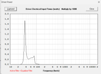
After input and simulation, i guess HR takes the driver power of the entire frequency range to calculate a mean value of maximum input in volts for an input of say 200° of voice coil temperature.
Is that correct ?
My idea is, that the excessive power input at well above 100Hz ( shown in pic 1 ), is out of interest with a subwoofer setup 30Hz-70Hz, therefore it would be great if there could be a selection not only of the temperature, but the frequency range for maximum temperature.
Ideally, the power compression function would also possible to apply AFTER the filter+EQ setup, therefore one would be able to compare power compression of different cabinets including setups with identical driver.
Thank you so much David for this software, do you have paypal, i would like to buy you some coffees at least !

After filtering the above ( grey ) vs. filtered response of a different cabinet with the same driver:

i have a question about the "Power compression" feature in HR. Of course, it depends largely on the voice coil size/material/cooling ability of each individual driver, but it is very useful to compare different designs with identical driver IMO.
My question is:
After input and simulation, i guess HR takes the driver power of the entire frequency range to calculate a mean value of maximum input in volts for an input of say 200° of voice coil temperature.
Is that correct ?
My idea is, that the excessive power input at well above 100Hz ( shown in pic 1 ), is out of interest with a subwoofer setup 30Hz-70Hz, therefore it would be great if there could be a selection not only of the temperature, but the frequency range for maximum temperature.
Ideally, the power compression function would also possible to apply AFTER the filter+EQ setup, therefore one would be able to compare power compression of different cabinets including setups with identical driver.
Thank you so much David for this software, do you have paypal, i would like to buy you some coffees at least !
After filtering the above ( grey ) vs. filtered response of a different cabinet with the same driver:
Attachments
Thanks for your reply David.
I am wondering if there is some tool in hornresp that will allow to superimpose a crossover slope over the horn response.
That would be useful to evaluate if the intended electrical xover slope is indeed possible, or if the "acustical" slope of the horn actually turns the electrical crossover into a higher order, due to intended xover slope becoming steeper when it meets the horn acustical slope.
I believe this is relevant to phase alignment at and around the xover.
Although this is probably offtopic in this thread it would be interesting for me to understand more about how horns DIY'ers go about addressing the massive phase shifts and delays which are inherent to horn loudspeakers design due to the slope of the horn response AND the relevant offset of the drivers in multiways systems.
- Home
- Loudspeakers
- Subwoofers
- Hornresp