Don't think that these are as problematic as you read on these forums. THe studies which tell you that these cchanges in the signals are audible are very controlled. Our ears are very forgiving when there is actual multi-tone music being played back.
I did a front loaded horn subwoofer that a few commented would have such massive group delay it would be horrendous. When they listened to it, a totally different story.
Now for midrange, if you are worried and you feed your speakers a signal via a computer you can use Rephase to make corrections. And there are a few stand alone DSP boxes that will accept the correction files as well.
My only guarded thoughts are to make comparisons be sure to do it blindfolded A/B/X type testing. It can be very humbling as to what you truly can hear, and what you believe that you hear.
Mark
I agree with Mark here.
When writing the Horn Book, I did some research into horn phase and time domain effects, and the audibility of phase and group delay in general. One thing that stood out in the listening tests that had been reported, is that these effects are quite subtle, and audibility is very dependent on the test signal, being most audible on computer generated test signals and clicks.
I also did tests myself, including making allpass filters to use with the convolver in FooBar. And you have to have quite large phase shifts before it's easily audible. Sensitivity to this is probably also very individual.
It is usually a good idea not to use midrange horns too close to their cutoff, I think crossing an octave or so above cutoff is often recommended. As for bass horns, this doesn't seem to be a problem. All the bass horns I have built have produced tight, clean and "fast" bass. Some work on bass quality in the time domain was done a few years ago by Lara Harris in her PhD study (see for instance https://eprints.soton.ac.uk/426110/), and for the book I had her run her method on simulated bass horns of various kinds. and the results actually came out on par with good closed box systems.
In practical use in a horn system (I have a fully horn loaded system myself), I have found time alignment (mechanical or digital) will improve the coherence of the system. I also prefer a "wide midrange" using big midrange horns and keeping the crossover away from the midrange.
Getting back on topic, Hornresp can simulate group delay, and can also overlay a curve developed by Klaus Futtrup on the limit for audible group delay.

This is the only place where I am getting sensible feedback on this subject.
On any other forum/thread everyone's advice is to go active with DSP and multiamp, and how much better it is and that's the only way to fix phase and timing and it will sound horrible if you don't and blah blah blah.
No matter how much I stress that is not the way I want to go, the answer is always the same. Looks like everyone forgot how horn systems were designed before DSP and cheap Class D amps were invented.
Now, I am perfectly aware that would be the easiest, better and most effective way to manage these issues, but on the other hand, since we're talking a 4 way high efficiency system in home environment (80db), the use of 4 power amps sounds to me like using a flame thrower to take down a mosquito. And after reading Mark and Kolbrek's reply I am starting to wonder if the mosquito is really in the room at all.
So I am seriously considering Mark's suggestion to go with a "normal" crossover and then fix the phase issues with rePhase. That would not require designing and fine tuning complicated passive xovers and would still address phasing, although in an unconventional manner that will be frowned at by the "purists".
But since listening to music is not an exercise of style in designing electronic circuitry (many will object to such sentence...) who cares the style as long as the result is good.
So... I wonder if this approach would be suitable for a 4 way system with a direct radiation woofer and horn loaded two mids and high crossed at about 200, 900, 5000.
Phisical alignment of the drivers at 1 or 1/2 wave length (180° or 360° phase shift) of the xover frequency should be feasible, as well as crossing one octave or more within the horns cutoff range.
I wonder what order filter would be be advisable in such scenario. I'd be happy if I could go with a second order, but I am aware higher orders might be better choice, to stay well within the horns acoustic cutoff.
I'm sorry about the OT, I hope it will be tolerated, but as I said this is the only place where I am getting sensible replies.
I do work with passive crossovers from time to time. But, it is getting to the point that the active system that is potentially superior in many ways is cheaper than a reasonably made passive. I do not believe that fancy caps and inductors listened to in a blind test will perform any better than well chosen quality caps and inductors. ABX testing that is truly blind to both tester and conductor of the test prove that. If you have read enough about crossovers, you will know that a passive crossover introduces it's own problems. Being shifting crossover points over different driver temperatures. And their own phase changes in the output of each driver that changes with frequency.So I am seriously considering Mark's suggestion to go with a "normal" crossover and then fix the phase issues with rePhase. That would not require designing and fine tuning complicated passive xovers and would still address phasing, although in an unconventional manner that will be frowned at by the "purists".
But since listening to music is not an exercise of style in designing electronic circuitry (many will object to such sentence...) who cares the style as long as the result is good.
Not saying that you can't do it. Just do a cost/performance analysis. In private work I do I honestly charge more for passive crossover design. It is a lot more difficult to do it right. The last really good one we did is 17 components for a 2 way. Sounds really good. And measures well. But there be a lot of parts. Even at reasonable part cost is it near the cost of a DSP.
Lastly if you do go DSP. MiniDSP has a few that are so limited in their abilities that you will pull out the last hairs on your head that you have left !!! Not possible on my head any longer 🙂
Mark
You don't have to go all active or all passive, it's quite possible to mix. I haven't done passive crossovers for years, and I've actually never used it for my horn rig, since everything, like level adjustments, response shaping and crossover frequencies are much more easily changed in an active setup, and there is less interaction with the driver, which means you can use values closer to text book values. I started out with tube based active filters, and I'm now running a BSS Blu100 DSP.
If you want to go the passive route, do you have experience with passive crossovers? Passive 4-way crossovers? If you have your methods nailed for a successful design of a 4-way passive XO, a 4-way passively crossed horn rig may be the next exciting challenge to take on. If you haven't done much passive crossover designs before, or nothing more complex than a two-way, you may want to ask yourself if fiddling with passive crossovers is something you really love doing. Because there will be a learning curve and much frustration over a long time, I'm sure. I also recommend using as complete measurements as possible and design the thing in software like VituixCAD as a starting point.
Another approach is to dial in the system using DSP, and then construct a passive solution that does about the same. That will probably save you some work. VituixCAD will again be a useful tool.
As mentioned you can mix: passive mid/tweeter for instance, or midbass/mid, doing the bass crossover actively. That will simplify the passive design. Also try to time align things not just to the phase at the crossover frequencies, but to the arrival times. Aligning to phase is IMO just damage control, not a good solution. If you don't time align to arrival times, especially transients will be smeared. The tests done by Hilliard in the 30s showed that 1ms difference in arrival time is audible. I think that was tested using a direct microphone feed, so it should be applicable to modern high-res recordings as well.
For amplifiers, I have no experience with class D amps in my system (apart from one case, where a small, cheap amp turned out to be so noisy that my horn system sounded like a waterfall), but you don't need much power. It will be mostly in the low milliwatt range. (I'm planning to build a power meter to measure actual power delivered to the speakers to get the real values, but simple 'scope peak voltage measurements indicate less than 100mW when playing really loud.) Small class A amps of a few watts, maybe a slightly bigger one for bass, will be enough for most situations. Especially for your use where you mention a 80dB listening level. But beware of transients, they may not contain much power, but you need the peak voltage.
Lastly, it's of course possible to take the happy-go-lucky approach and design a passive system without measurements, using simple filters, lots of listening and patience, swapping parts until it "sounds good"...
Mark and Kolbrek, thank you so much for your reply.
The reason why I would prefer a passive is simply because I would like to use on the whole range a dual block 100+100 tube amp I purchased recently and love how it sounds. I am not fond of mixing solid state (of which i have 4) and tube amps, and would really try to avoid buying 2-3 more tube amps. I did not mention in my previous post that I wouldn't mind driving the woofer (0-200) with a SS, but I'd rather not mix tubes and SS on the rest of the range. So a 3 way passive would be perfectly fine. I may even evaluate the purchase of a "twin" of the tube amp if that is REALLY necessary but not more than that.
Not sure if a 3 ways vs 4ways filter would make things much easier anyway, if it is indeed necessary to do all the time alingment and phase correction via the passive filter as you seem to suggest.
One more reason of the idea to go passive lies in the fact that I have a tube preamp (which I'd rather not scrap), and a DAC between the source and the preamp (which I'd rather not scrap either)
So a DSP would result in extra ADC-DAC conversions before the power amps.
I also have a two ways analog active crossover @ 12db/oct. I wonder if this could be used to do simulations and all kinds of measurements with REW before designing the actual 3 (or 4) ways passive. I don't have specific experience with 4 ways and for horn specific crossovers. I've built before 3 ways filters for direct radiation loudspeakers before, but I'm aware that horns will require a different approach due to phase and timing (and maybe also to impedance). Also T-S parameters and impedance are not available for compression drivers and that also makes things a little different.
PS. @ Kolbrek
Arrival time...actual delay at the listening point ?
Won't that mean taking also the listening room contribution into account ?
REW, USB mic of your choice, Vituix and you can start at it. Reasonable amount of bucks to do it. The mic is the only expense. Don't get the extra calibration types. Your microphone movement between measurements is more a factor than the top end calibration. I have 14 mics, and use many. But my go to has been my UMIK for the past year. I will get a better one next time I'm in China, or if I am momentarily too wealthy 🙂
Mark
Mark
I've already got a Behringer 8000 and Behringer UM2 interface. It doesn't have calibration file but hearsay is it's flat enough for the purpose.
I looked at some vituixcad tutorials, but they all start with T-S parameters, which are not available for compression drivers and not sure they make sense even for cones when horn loaded.
I looked at some vituixcad tutorials, but they all start with T-S parameters, which are not available for compression drivers and not sure they make sense even for cones when horn loaded.
VituixCAD can import measured values for the electrical impedance and frequency response/directivity of each driver/horn. That is how I suggest you use it when you have the actual system components at hand.
TS-parameters are useful in the initial design. But often the parameters you find in data sheets don't have an accurate enough inductance model or suspension creep included, and I've found this to be quite important sometimes, especially the inductance model. Lumped models of compression drivers work up to the frequency where the diaphragm breaks up, but they are not straightforward to measure (the best is to use a vacuum chamber and a velocity laser - not cheap!).
TS-parameters are useful in the initial design. But often the parameters you find in data sheets don't have an accurate enough inductance model or suspension creep included, and I've found this to be quite important sometimes, especially the inductance model. Lumped models of compression drivers work up to the frequency where the diaphragm breaks up, but they are not straightforward to measure (the best is to use a vacuum chamber and a velocity laser - not cheap!).
PS. @ Kolbrek
Arrival time...actual delay at the listening point ?
Won't that mean taking also the listening room contribution into account ?
Yes, actual delay to the listening point. Make everything arrive in synch. Usually you get pretty close using the acoustical distances from the voice coils, but I think REW has a feature to help time align drivers as well.
Time alignment is only important for the direct sound, so you don't need to take room effects into account. That would be impossible anyway, since the required delay would be different depending on which reflections you considered.
David, I'm running into some "strange" errors in Hornresp, that I'd like to bring to your attention.
Let's start by using the "TL design" feature.
First I create a new record and call it "TL Design"

Then I select the "Paste Driver from Database" option to select one of my sample drivers, in this case an Alpine Type R...

Then I select the "TL Design option... " and the "BS 2002' method and then select "Save"


The first thing that sticks out at me is that "Ang" hasn't changed. It should be changed to 2.0xPI. The methods provided by Martin King and myself assume 2xPI loading (well, for my method yes. I'm fairly certain it's assumed for MK's methods as well).
Issues also arise when the number of drivers is changed (e.g. from 1 to 2) ...

Now, when I go into the "Schematic" view, it's no longer showing an OD alignment (note the position given for the driver). And L23 is no longer automatically adjusted when L12 is changed....


I've seen other sporadic errors turn up in the model as well, and they all seem to originate with changing the number of drivers.
Let's start by using the "TL design" feature.
First I create a new record and call it "TL Design"
Then I select the "Paste Driver from Database" option to select one of my sample drivers, in this case an Alpine Type R...
Then I select the "TL Design option... " and the "BS 2002' method and then select "Save"
The first thing that sticks out at me is that "Ang" hasn't changed. It should be changed to 2.0xPI. The methods provided by Martin King and myself assume 2xPI loading (well, for my method yes. I'm fairly certain it's assumed for MK's methods as well).
Issues also arise when the number of drivers is changed (e.g. from 1 to 2) ...
Now, when I go into the "Schematic" view, it's no longer showing an OD alignment (note the position given for the driver). And L23 is no longer automatically adjusted when L12 is changed....
I've seen other sporadic errors turn up in the model as well, and they all seem to originate with changing the number of drivers.
Hi Brian,
Many thanks for the feedback.
Because the dimensions calculated by the TL Design tool models are independent of the specified Ang value I had assumed that there was no need to set it to a particular value. As a result of your comments however, in the next update Ang will be set to 2 x Pi when the TL Design tool is used.
I have found the bug and it will be fixed in the next update.
If you happen to identify any more of the sporadic errors, could you please let me know. One thing to be aware of is that advanced driver parameter values are not taken into account in the TL Design tool and are switched off when results are saved back to the main input parameters window.
Thanks again for the valuable feedback!
Kind regards,
David
Many thanks for the feedback.
The first thing that sticks out at me is that "Ang" hasn't changed. It should be changed to 2.0xPI. The methods provided by Martin King and myself assume 2xPI loading (well, for my method yes. I'm fairly certain it's assumed for MK's methods as well).
Because the dimensions calculated by the TL Design tool models are independent of the specified Ang value I had assumed that there was no need to set it to a particular value. As a result of your comments however, in the next update Ang will be set to 2 x Pi when the TL Design tool is used.
Issues also arise when the number of drivers is changed (e.g. from 1 to 2) ...
I have found the bug and it will be fixed in the next update.
I've seen other sporadic errors turn up in the model as well, and they all seem to originate with changing the number of drivers.
If you happen to identify any more of the sporadic errors, could you please let me know. One thing to be aware of is that advanced driver parameter values are not taken into account in the TL Design tool and are switched off when results are saved back to the main input parameters window.
Thanks again for the valuable feedback!
Kind regards,
David
Hi Brian,
After giving it some further thought, perhaps it would be best to leave things as they are 🙂.
As indicated in my previous post, the system dimensions calculated by the TL Design tool models are independent of the Ang value setting. Also, before the TL Design tool opens a message is displayed prompting the user to check that they have specified the correct Ang value, as shown below.

If the user intends positioning the transmission line loudspeaker on the floor against a wall, then it seems to make sense to allow Ang = 1 x Pi to be specified in the TL Design tool so that the calculated results reflect the intended location, rather than setting Ang = 2 x Pi for all cases.
The first image below shows the 2 x Pi power response obtained using the BS 2022 method with usable bandwidth = 5. The second image shows the 1 x Pi power response obtained using the same method and bandwidth.


Given the above comments, can you see any problems in leaving things as they are?
Kind regards,
David
in the next update Ang will be set to 2 x Pi when the TL Design tool is used
After giving it some further thought, perhaps it would be best to leave things as they are 🙂.
As indicated in my previous post, the system dimensions calculated by the TL Design tool models are independent of the Ang value setting. Also, before the TL Design tool opens a message is displayed prompting the user to check that they have specified the correct Ang value, as shown below.
If the user intends positioning the transmission line loudspeaker on the floor against a wall, then it seems to make sense to allow Ang = 1 x Pi to be specified in the TL Design tool so that the calculated results reflect the intended location, rather than setting Ang = 2 x Pi for all cases.
The first image below shows the 2 x Pi power response obtained using the BS 2022 method with usable bandwidth = 5. The second image shows the 1 x Pi power response obtained using the same method and bandwidth.
Given the above comments, can you see any problems in leaving things as they are?
Kind regards,
David
The estimates for optimum Fb are based on 2*PI space but going by the sim'd results the only thing that noticeably changes at low frequencies is amplitude, so I'd leave it as it is.

The estimates for optimum Fb are based on 2*PI space but going by the sim'd results the only thing that noticeably changes at low frequencies is amplitude
Fb in the BS 2022 method is calculated as shown below, using driver parameter values only. The power response level will change due to the different loading conditions (which are dependent upon the value chosen for Ang).
Vb = 20 * Qts ^ 3.3 * Vas
Fb = (Vas / Vb) ^ 0.31 * fs
so I'd leave it as it is.
Excellent. The 'missing OD alignment' bug you found will of course still be fixed in the next update.
I have a few questions regarding the profile design. Front loaded mid-bass horn, 200 to 1000Hz, home use.
Is there any difference in the horn response when choosing a rectangular horn profle vs the "standard" profile proposed by Hornresp ? Also, how the widht flare (con - exp - uni) has an influence (if any) on the horn response ?
With regard to "bent" horns, I read somewhere that this should be avoided, but I see plenty curved horns. Is there any rule that one is supposed to follow to "bend" a horn so that this doesn't influence the response too much ? I am talking rounded "bend" in a front loaded not "fold" as most back loaded.
Should the bend be distributed throughout the whole lenght or it can be implemented at some point around the middle of the horn (provided that the bend is not tight) so that the segments near the throat and the mouth are rectilinear ?
The idea is to wrap a 140-160 cm mid bass horn around the top and back of the box that hosts the woofer, with the driver pointing upward. This would result in a 90° bend at about half the lenght of the horn. A mid-high horn goes on top of it.
I've been trying to model a 80-90cm horn for two days (with several drivers) so I don't have to bend it, but I lost hope as in no way I can make it nice and linear down to 100Hz (so it can be crossed at 200).
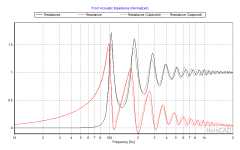
There is a difference in how the mouth radiation impedance (and therefore the reflections from the mouth) behave in circular vs rectangular horns. They are pretty similar when the horn is square, but as it becomes more rectangular, with a larger aspect ratio, you need a somewhat larger mouth area for the same level of reflection. In general, horn mouth size for a circular horn should be about one cutoff wavelength in circumference (Cir = 1), as the horn is placed near walls and floor, the required physical area is reduced. Hornresp automatically adjusts Cir when Ang changes so that Cir = 1 would produce about the same level of reflections for all values of Ang.
Cir = 1 means the diameter is one third cutoff wavelength. For a rectangular horn with an aspect ratio different from 1, the smallest dimension should be one third cutoff wavelength for the same level of reflection. The first attachment shows the difference in throat impedance between a circular exponential horn (overlay) and a rectangular horn with an aspect ratio of 1:3 (H:W). The difference is not huge, and only really becomes important for fairly large aspect ratios.
Also, when a horn is placed near boundaries, these boundaries act like acoustic mirrors, and the total mouth area is the sum of the physical horn mouth and all the mirror images. This means that the effective mouth aspect ratio should be taken from the total, not just the physical horn. A horn with an aspect ratio of 1:1 (H:W) placed on the floor, will have an effective aspect ratio 2:1 and so on.
The influence of the width flare is small, no noticeable effect on reflections unless you get a very pinched throat part. Directivity will change a little, but the horn doesn't have much control over directivity in this range anyway.
When it comes to bends, bends are better than folds, and large bends are better than tight ones. Usually folds create big dips and notches in the response, sometimes quite wide ones too. With bends it's easier to get a wideband response. A couple of years ago, I build a bass horn with two bends, which has smooth response up to 900Hz (this is just looking at the smoothness, it starts to roll off above 600Hz). See Big Bend horn performance measurements. The blog article series may have some other info that's useful to you.
Attachments
Hornresp Update 5460-230422
Hi Everyone,
BUG FIX
The 'missing OD alignment' problem reported in Post #13,490 has now been fixed.
My thanks to Brian for the feedback.
Kind regards,
David
Hi Everyone,
BUG FIX
The 'missing OD alignment' problem reported in Post #13,490 has now been fixed.
My thanks to Brian for the feedback.
Kind regards,
David
Hello David,
I'm a new Hornresp user and really like your work, thank you.
I've been trying to use Hornresp for micro speaker simulation, but somehow can't input accurate chamber volumes below 0.0005 Ltrs, (On AJ Horn I am able to input very small values). Also how we can view the loudspeaker wizard simulation above 2000Hz? I would really appreciate your help. Thanks
Regards,
GQZ
Hi GQZ,
Pleased to hear that you like Hornresp 🙂.
Double-click on the Vrc label in Edit mode to select the cubic centimetre option. You can then specify a rear chamber as small as 0.01 cm^3 (10 mm^3). The standard minimum value for the throat chamber volume Vtc is also 0.01 cm^3 (10 mm^3).
Double-click on the Loudspeaker Wizard Frequency (hertz) chart label. Not applicable when absorbent filling material is included.
Kind regards,
David
I'm a new Hornresp user and really like your work, thank you.
Pleased to hear that you like Hornresp 🙂.
I've been trying to use Hornresp for micro speaker simulation, but somehow can't input accurate chamber volumes below 0.0005 Ltrs
Double-click on the Vrc label in Edit mode to select the cubic centimetre option. You can then specify a rear chamber as small as 0.01 cm^3 (10 mm^3). The standard minimum value for the throat chamber volume Vtc is also 0.01 cm^3 (10 mm^3).
Also how we can view the loudspeaker wizard simulation above 2000Hz?
Double-click on the Loudspeaker Wizard Frequency (hertz) chart label. Not applicable when absorbent filling material is included.
Kind regards,
David
Kolbrek, thank you very much for your reply, which I took some time to elaborate.
It is not clear to me if one should take into account the acoustical power diagram indipendently of the Cir value or viceversa.
I have modeled two horns. One with Cir = 1 and another with Cir= 0,83, the second one being MUCH smaller and a little shorter.
The difference in the acoustical power diagram is marginal and it happens on the top corner of 100Hz on a horn which is supposed to be crossed at 200, so that "difference" should be well above the actual crossover curve. For this reason I'd rather trade that small difference at 100hz for a much smaller mouth and shorter lenght. See attachments below
Big Mouth Long Horn 4700/164 (Cir =1).

Small Mouth and shorter horn 2800/140 (Cir = 0,83)

Big Mouth Long Horn 4700/164 (Cir =1).

Small Mouth and shorter horn 2800/140 (Cir = 0,83)

Now if I make the "small horn" rectangular this results in 70x40(height)cm. horn size.
Wavelenght at actual crossover frequency of 200Hz is 1.725 which divided by 3 = 0,575 which is larger than the calculated 40cm height.
That's of course even worse if I take into account wave lenght at 100Hz, (that is one octave below actual crossover point).
Now the question is, how is that supposed to impact on the actual horn response, considering actual crossover point (200) and that the hornresp manual reads as follow:
In most modern horn designs the actual mouth area is smaller than the optimum mouth area (most often a compromise between gigantic size and actual performance needed). About the reasoning behind this you can find more information in the Speakerplans FAQ's and general horn theory found on the www. In short you can get away with a CIR smaller than 1.0 without degrading performance to much if designed correctly.
I guess the problem lies in the words "designed correctly".
In this regard the horns I designed appear to be MUCH more linear than the average midbass horns I've seen on the www, as most are not nearly as flat in the intended range (actually they all appear all "rounded"). Can mine be considered a "correct design" ? Too conservative ? (i.e. not required to be so flat).
The reason i am concerned about linearity at one octave from actual crossover points is that i read (and was warned) that acoustical cutoffs too near (less than one octave) from the actual electrical crossover points result in massive phase shifts at the electrical crossover point, which I'd rather avoid if possible.
Also it is not clear to me what the actual Ang value should be in "real life" home environment. This horn is to be placed on the woofer box at 90cm from the floor and the back wall, and 70cm from the side wall. I considered Ang as 2.0 x Pi (as average).
Is this correct or should I consider 1,0 x Pi (or maybe 1.5) due to the horn being relatively close to a corner ? As you explained this would result in the possibility to go for the smaller horn wihout much worries.
Also the hornresp manual suggests a Ang value of 1,0 x Pi for Hi-Fi applications so perhaps I am indeed being too conservative even on the Ang. value ?
I also have some questions about the "matching impedance" of the driver and horn you mention on your blog, but let's discuss one problem at a time.
Thank you for your patience and MUCH appreciated cooperation.
It is not clear to me if one should take into account the acoustical power diagram indipendently of the Cir value or viceversa.
I have modeled two horns. One with Cir = 1 and another with Cir= 0,83, the second one being MUCH smaller and a little shorter.
The difference in the acoustical power diagram is marginal and it happens on the top corner of 100Hz on a horn which is supposed to be crossed at 200, so that "difference" should be well above the actual crossover curve. For this reason I'd rather trade that small difference at 100hz for a much smaller mouth and shorter lenght. See attachments below
Big Mouth Long Horn 4700/164 (Cir =1).
Small Mouth and shorter horn 2800/140 (Cir = 0,83)
Big Mouth Long Horn 4700/164 (Cir =1).
Small Mouth and shorter horn 2800/140 (Cir = 0,83)
Now if I make the "small horn" rectangular this results in 70x40(height)cm. horn size.
Wavelenght at actual crossover frequency of 200Hz is 1.725 which divided by 3 = 0,575 which is larger than the calculated 40cm height.
That's of course even worse if I take into account wave lenght at 100Hz, (that is one octave below actual crossover point).
Now the question is, how is that supposed to impact on the actual horn response, considering actual crossover point (200) and that the hornresp manual reads as follow:
In most modern horn designs the actual mouth area is smaller than the optimum mouth area (most often a compromise between gigantic size and actual performance needed). About the reasoning behind this you can find more information in the Speakerplans FAQ's and general horn theory found on the www. In short you can get away with a CIR smaller than 1.0 without degrading performance to much if designed correctly.
I guess the problem lies in the words "designed correctly".
In this regard the horns I designed appear to be MUCH more linear than the average midbass horns I've seen on the www, as most are not nearly as flat in the intended range (actually they all appear all "rounded"). Can mine be considered a "correct design" ? Too conservative ? (i.e. not required to be so flat).
The reason i am concerned about linearity at one octave from actual crossover points is that i read (and was warned) that acoustical cutoffs too near (less than one octave) from the actual electrical crossover points result in massive phase shifts at the electrical crossover point, which I'd rather avoid if possible.
Also it is not clear to me what the actual Ang value should be in "real life" home environment. This horn is to be placed on the woofer box at 90cm from the floor and the back wall, and 70cm from the side wall. I considered Ang as 2.0 x Pi (as average).
Is this correct or should I consider 1,0 x Pi (or maybe 1.5) due to the horn being relatively close to a corner ? As you explained this would result in the possibility to go for the smaller horn wihout much worries.
Also the hornresp manual suggests a Ang value of 1,0 x Pi for Hi-Fi applications so perhaps I am indeed being too conservative even on the Ang. value ?
I also have some questions about the "matching impedance" of the driver and horn you mention on your blog, but let's discuss one problem at a time.
Thank you for your patience and MUCH appreciated cooperation.
Last edited:
- Home
- Loudspeakers
- Subwoofers
- Hornresp