Don't suppose you've got Vitavox S2 params up your sleeve? 🙂
Just checked - all I could find was my elbow 🙂.

Thank you David, and what value should be entered in the Vel box ?If driver parameter values are not available then use the constant diaphragm velocity (Vel) option.
(Double-click the Eg label in Edit mode to select the Vel option).
After switching from Eg to Vel it defaults at 0,10 (with an Eg value of 2.83). The lower half of the window (TS parameters) must all be set to zero ?
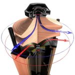
With regards to horns with a curved mouth profile, such as the TAD horn attached above, I assume one should consider the round surface as the actual mouth surface and what would be the benefit of that profile on a mid-bass horn ?
That round profile is commonly found on mid-range horns with a 600hz lower cutoff, so I think it should make sense also on a mid-bass horns which extends to such frequencies (or higher).
Hello David,
How is the time taken for the front and back waves to meet, in a U-Frame, calculated in Hornresp?
How is the time taken for the front and back waves to meet, in a U-Frame, calculated in Hornresp?
The acoustic center concept from John Vanderkooy’s set JEAS papers is used. Some details were posted here: Post#9986
So I assume that is supposed to be the "starting point" for any horn model, while the rest of the data (horn mouth. lenght, VRC etc. can more or less be adjusted in order to obtain a flat response in the power response window.
Basically yes.
In this case, can electrical and acoustical impedance diagrams be disregarded as the matter has already been taken care of in a different, more specific manner ?
Acoustical impedance can be a tool to check how resonant the horn is, but it's more useful after you get some more experience. Try different versions (just adjusting the length is enough for this) to get a feel for what happens when the mouth is too small (low Cir) etc.
And is there anything else that would require further optimization before I purchase the drivers and start the woodworking ? What about delay and phase ?
Check the delay curve against the Futtrup curve, and make sure displacement stays acceptable.
PS.
More in general but still with regards to TS parameters....how is one supposed to go about modeling a Mid or High frequency horn based on a compression driver, since for those no TS parameters are available ? Nor they can be measured with REW or DATS since it impossible to add a weight to the cone as it is done with cone speakers.
As mentioned before, it takes some specialized measurements to get it right. There are some papers about compression drivers that give values, but usually you can't get them.
Of course you can, how else do you think they are designed? 🙂I don't believe you can model compression drivers.
At Celestion we used FEA for that, mainly. But I also did work on lumped parameter modelling, and measuring the driver transfer matrix (voltage and current in, pressure and volume velocity out, this can be pretty accurate, and I have gotten within 1dB with a good horn model. This method is used for the frequency response calculations in the Celestion Horn Wizard, although the horn model there is fairly simple to optimise speed).
As for lumped parameter modelling, I measured the mechanical parameters in a vacuum chamber using a Polytec velocity laser, then added the acoustical model on top of that using the in-house modelling software we had. The results were quite accurate below the diaphragm breakup frequency. Unfortunately this is methods out of reach for most hobbyists. My point is that it is possible and can get pretty close.
Yeah, I meant by folk like me using Hornresp, not having access to published T&S data for any driver we chose to want to model.
That is your 2nd to last statement.
If you have the data I can use for S2's, JBL range etc, please share🙂
That is your 2nd to last statement.
If you have the data I can use for S2's, JBL range etc, please share🙂
what value should be entered in the Vel box ?
The default value of 0.10 metres per second is usually sufficient for most purposes.
Using a different value will simply change the power response and diaphragm displacement levels.
The lower half of the window (TS parameters) must all be set to zero ?
When the Vel option is selected the driver parameters are disregarded. The existing values do not have to be adjusted in any way.
With regards to horns with a curved mouth profile, such as the TAD horn attached above, I assume one should consider the round surface as the actual mouth surface
As far as Hornresp simulations are concerned, the plane rectangular surface just before the upper and lower curves commence should be considered as the horn mouth (this also defines the horn length).
what would be the benefit of that profile on a mid-bass horn ?
Not sure that there would be much practical benefit at those frequencies, but perhaps try Googling 'radial horn' to see if you can find a definitive answer.
David, you mention in your reply that in hornresp it is the actual rectangular surface of the mouth that should be taken into account.
Of course you are the designer of the software and know how it works, however I am not sure that a radial horn modeled in horn resp would not be reasonably accurate.
If one considers an omnidirectional horn such as the one attached below, it is obvious that the horn lenght is dictated by the horn radius and that the surface of the throat is necessarily the surface of the cilinder that spans from the upper to the lower "lip" of the mouth.
This same approach can be applied to multicellular and sectoral radial horns, which are basically a number of small horns arranged in an array aimed at improving dispersion and increasing the overall mouth surface to reproduce lower frequencies. So, the lenght in multicellular/sectoral horns is actually dictated by the radius while the surface is the sum of the "small horns" surfaces. A radial horn is not much different from a multicellular/sectoral horn at least with regard to lenght (=radius) and surface of the mouth.
I wonder if these considerations can be taken into account (and how) in order to model a radial horn in hornresp, or even an omnidirectional, which I have been thinking about since a while.
@ Kolbrek, after going a few times thru your article "My approach to bass horn design" the pieces of the puzzle are starting to click.
I wonder if you could elaborate on the relationship of the horn calculation with a tube amp which you briefly mentioned in your article.
Also I wonder, due to your cooperation with celestion, if you have the data for their range of compression drivers or if they can somehow be obtained from the company.
If one is supposed to model a horn from scratch and has to buy the driver, I guess a good starting point would be purchasing a driver that comes with the parameters required to be matched to a specific horn, or adjust the horn to match the driver.
Attachments
Tube amps generally have higher output impedance that solid state amps, and that should be taken into account when calculating the impedance matching. This is done simply by adding the amp output impedance to Re in the calculations. And it may be a good idea to add the wiring resistance as well, and if you use passive crossovers, you can add the coil DC resistance. An advantage of this is that the resistance of the crossover components can be compensated for, so that super low DC resistance isn't necessary.
I'm not sure if I still have some data from Celestion, but I'll have a look.
But when modelling a horn for a compression driver, the driver parameters aren't that helpful, since you can't adjust the compression ratio or compression cavity volume. The rear chamber volume can be adjusted, but it usually doesn't matter much, since you wouldn't use the horn close to cutoff anyway.
The most important parameter would be the input area and length of the internal flare, from the phase plug slits to the driver exit, to make sure you don't create too strong standing waves in the driver-horn combination.
David, you mention in your reply that in hornresp it is the actual rectangular surface of the mouth that should be taken into account.
By mid bass I thought that you had in mind something like the square cross-section horn design shown below, but with the top and bottom panels extended to form curved "lips". In other words, a relatively short horn with a relatively large throat, having a cone type driver.
Even though it could be argued that the above horn design has the general profile of a radial horn, at the frequencies involved it would not really act like one. That is why I said that I was not sure that the curved lip extensions would be of much practical benefit given the intended frequency range.
A mid range or high frequency radial horn design on the other hand, particularly if using a compression driver, would normally be analysed with the curved surface being taken as the mouth area, as you assumed. The same principle would apply to a mid range / high frequency multi-cellular or sectoral radial horn.
In Hornresp, if so desired vacuum tube amplifier output impedance can be specified separately as Rg rather than being added to Re 🙂.This is done simply by adding the amp output impedance to Re in the calculations.
In Hornresp, this can be specified to a reasonable degree using the throat chamber and throat adaptor, as shown below.The most important parameter would be the input area and length of the internal flare, from the phase plug slits to the driver exit
In Hornresp, if so desired vacuum tube amplifier output impedance can be specified separately as Rg rather than being added to Re 🙂.
I meant when calculating the throat area for impedance matching. For simulations, you would of course add this in Hornresp 🙂
You made that quite clear in your post - I should have read it more carefully! 🙂I meant when calculating the throat area for impedance matching
Hornresp Update 5460-230508
Hi Everyone,
CHANGE
A minor change has been made to the message displayed in the status bar panel at the bottom of the Input Parameters window when the mouse pointer is moved over the throat area of a stepped segment. As an example, when the mouse pointer is moved over the throat area of stepped segment 2 the message now starts with S2S as shown below, rather than with just S2 as was the case previously.

BUG FIX
When Vrc was specified in cubic centimetres the Helmholtz resonance frequency shown in the Loudspeaker Wizard was not correct:

This bug has now been fixed:

Kind regards,
David
Hi Everyone,
CHANGE
A minor change has been made to the message displayed in the status bar panel at the bottom of the Input Parameters window when the mouse pointer is moved over the throat area of a stepped segment. As an example, when the mouse pointer is moved over the throat area of stepped segment 2 the message now starts with S2S as shown below, rather than with just S2 as was the case previously.
BUG FIX
When Vrc was specified in cubic centimetres the Helmholtz resonance frequency shown in the Loudspeaker Wizard was not correct:
This bug has now been fixed:
Kind regards,
David
@ Kolbrek, not sure what you mean with this.Check the delay curve against the Futtrup curve, and make sure displacement stays acceptable.
I googled Futtrup curve and the only relevant result is some papers published by Futtrup which require AES membership to be accessed.
I googled Futtrup curve and the only relevant result is some papers published by Futtrup which require AES membership to be accessed.
If you want any AES papers I can get them.
Mark
@ Kolbrek, not sure what you mean with this.
I googled Futtrup curve and the only relevant result is some papers published by Futtrup which require AES membership to be accessed.
See http://cfuttrup.com/blogspot/Book_05_Futtrup.pdf, Futtrup describes it as "This chapter is somewhat like a "layman's" version of the AES paper I wrote in 2011, targeting a nontechnical audience, (almost) without the math. It adds historical background and some idea about how to ensure a nice impulse response by using Group Delay." So this is where the group delay curve comes from, it was not in the original AES paper.@ Kolbrek, not sure what you mean with this.
I googled Futtrup curve and the only relevant result is some papers published by Futtrup which require AES membership to be accessed.
- Home
- Loudspeakers
- Subwoofers
- Hornresp